
Related Manuals for Shinhoo GPA-II Series


Summary of Contents for Shinhoo GPA-II Series
- Page 1 GPA-II Series Energy-saving Pipeline Canned Motor Pump Installation and Operation Manual Hefei Xinhu Canned Motor Pump Co., Ltd.
- Page 2 Notes: 01. Read the installation manual 11. Some models are not suitable for carefully before installation and drinking water. use. 12. The liquid may be high-temperature 02. The manufacturer will not be liable and high-pressure; therefore, the for any personal injury, pump liquid in the system must be damage and other proper ty completely drained or the shut-off...
- Page 3 and abnormality of motor is detected, and contact your vendor or service center immediately. 19. If trouble cannot be addressed according to the manual, please close the valves on the inlet and outlet of the pump immediately, cut off power supply and contact your vendor or service center immediately.
- Page 4 2. General 2.1. GPA series circulation 2.2. Advantages motor pump is mainly Easy installation and start-up used in domestic heating · Provided with self-adaptive mode and hot water system. AUTO The product is most applicable to the Initial setting). In most cases, the following systems: motor pump needs no adjustment ·...
-
Page 5: Operating Conditions
3. Operating Conditions 3.1 Ambient Temperature ℃ ~+ ℃ Ambient temperature: 0 3.2. Relative humidity(RH): Max. humidity: 95% 3.3. Medium (liquid delivery) temperature ℃ ℃ Liquid delivery temperature: +2 To avoid condensation in control box and the stator, the temperature of liquid pumped by the motor pump must be always higher than ambient temperature. -
Page 6: Installation
4. Installation 4.1. Installation · W h e n i n s t a l l i n g G PA s e r i e s circulation pump, the arrow on motor pump case indicates the flow direction of liquid through the pump. ·... - Page 7 4.2. Position of Junction Box 4.3. Changing Position of Junction Box 。 The junction box can be rotated in a step of 90° The procedures for changing the position of junction box are as follows: 1. Close the valves at the inlet and outlet and release the pressure; 2.
- Page 8 Warning Pumping liquid may be high-temperature and high-pressure; therefore, the liquid in the system must be completely drained or the valves on both sides of motor pump must be closed before removing the socket head screws. 4.4. Thermal Insulation of Motor Pump Body Limiting the heat loss of motor pump body and pipeline.
-
Page 9: Electrical Connection
5. Electrical Connection... - Page 10 Electrical connection and protection shall comply with local codes and norms. Warning The motor pump must be earthed The motor pump must be connected to an external power switch, and the minimum space between all the electrodes is 3mm. · GPA series circulation motor pump needs no protection from external motor.
-
Page 11: Control Panel
6. Control Panel 6.1. Controls on Control Panel Position Descriptions Indication lamp area in the Night Mode (AUTO). Button to start or turn off Night Mode (AUTO). Monitor that displays the actual power consumption of motor pump in Watt. Indication lamp area of eight operation modes set by motor pump. - Page 12 Button Times Indication Lamp Area Descriptions AUTO ( Initial setting Self-adaptive (AUTO) Lowest Proportional Pressure Curve Highest Proportional Pressure Curve Lowest Constant Pressure Curve Highest Constant Pressure Curve Ⅲ Constant Velocity Curve, Velocity III Ⅱ Constant Velocity Curve, Velocity II Ⅰ...
-
Page 13: Pump Setting
7. Pump Setting 7.1. Pump Setting Based on System Type Initial setting AUTO Self-adaptive mode Recommended and available pump setting Motor Pump Setting System Type Position Recommended Options Floor heating system 、 、 HD1 HD2 PWM AUTO Dual pipeline 、 BL2 PWM AUTO heating system... - Page 14 · It may take several minutes or even hours to reach the optimal operation mode after motor pump setting is changed from the optimal setting (the “Recommended abovemention”) to other optional setting. If the optimal setting of motor pump fails to enable each room to obtain desired heat distribution, then you should change the motor pump setting to other settings.
- Page 15 Night Mode (AUTO) 8.1. Basic Principle Warning Night Mode is unavailable for the GPA series motor pump installed in gas boiler heating system with small water capacity. If VelocityⅠ, VelocityⅡ, or Velocity Ⅲ mode have been selected, theNight Note Mode will be disabled; if PWM mode signal input is selected, then functions of other modes will be disabled.
-
Page 16: Night Mode Function
To ensure that the best status is realized in Night Mod, the following conditions must be satisfied: · The motor pump must be installed in the water inlet pipeline of the system and near the water outlet of boiler. · If the motor pump is installed in the water return pipeline of the system, then the Night Mode function will be disabled. - Page 17 9. PWM Signal Control Mode Duty Cycle( d%) 9.1. Control and Signal Mode T = 2 ms( 500Hz) t = 0.6 ms Control Principle d%=100×0.6/2=30% GPAXX-XX II model pump is controlled ~ = 4 24V by modulated LV PWM (Pulse Width ≤...
- Page 18 9.3. PWM Input S ignal 9.3.1 PWMi nputs ignalp rofil P WM1(heating) ·When PWM1 input signal is 0% or 100%, the · In area of high duty-cycle PWM1 pump will switch to non-PWM mode (normal signal, when the input signal mode), and the default system will have no fluctuates in the critical point, there will be a delay area to prevent...
- Page 19 9.3.2 PWM input signal profile PWM2(solar) · In area of low duty-cycle PWM2 signal, when the input signal fluctuates in the critical point, there will be a delay area to prevent frequent stop and start of the pump. · Without PWM2 signal percentages, the circulator will stop for safety reasons.
- Page 20 9.4. PWM Feedback Signal PWM feedback signal can provide operation status of the pump, such as power loss or all kinds of alarm/warning modes. PWM feedback signal will feed back exclusive alarming information. If the power voltage detects under voltage signal values, its output signal will be set to 75%. Provided sundries settlement exists in the hydraulic system and causes rotor being blocked, the duty cycle of output signal is set to 90%, the alarm will be given higher priority.
- Page 21 9.5. How to use the signals The signal can be used to measure power consumption of the pump. The pump signal can be used to detect the actual operating point of the system rather than measuring by the current controlled by the system. The signal is also applicable to comparing velocity setting value and feedback.
- Page 22 Bypass valve system installed between the Inlet pipeline and return pipeline 10.1. Purposes of bypass valve Chapter 7 Bypass valve The purpose of bypass valve: when all the valves and/or temperature-sensing valves of heat radiator in the floor heating loop are closed, it can ensure that the heat from boiler can be distributed.
- Page 23 10.2. Manually-operated Bypass Valve In accordance with the following procedures: 1. When regulating bypass valve, the pump shall be in Setting I (Velocity I Mode). The minimum flow rate(Q min) of the system shall be always guaranteed. Please refer to bypass valve manual provided by the manufacturer.
- Page 24 11.2. Exhaust the Motor Pump GPA series motor pump is equipped with self-venting function. Before the start up, it is not necessary to vent the air. Air in the motor pump may cause noise. After the motor pump is put into operation for several minutes, the noise will disappear.
- Page 25 12. Motor Pump Setting and Performance 12.1. Relations between Pump Setting and Performance PWM mode performance running area (Gear I-Gear III) Pump Characteristics Setting Functions Curve AUTO function will automatically control the pump performance within the specified scope. Highest to Lowest adjust pump performance based on system scale;...
- Page 26 Pump Setting Characteristics Functions Curve The operating point of the pump will move around the Lowest Constant lowest constant pressure curve based on the demand Pressure Curve of system flow rate. The supply pressure of pump remains constant and it is irrelevant with the flow rate. The operating point of the pump will move around the Highest highest constant pressure curve based on the demand...
-
Page 27: Performance Curve
13. Performance Curve 13.1. Guide on Performance Curve Every setting of the motor pump has corresponding performance curve (Q/H curve). However AUTO (Self Adaptive Mode) mode covers just one performance scope. The area of PWM signal control performance curve (Q/H curve) is between motor pump velocity I-III. - Page 28 13.3. GPA××-4 Series Performance Curve GPAXX-4 II Performance Curve GPAXX-4 II PWM Signal Control Performance Curve...
- Page 29 13.4. GPA××-5 Series Performance Curve GPAXX-5 II Performance Curve GPAXX-5 II PWM Signal Control Performance Curve...
- Page 30 13.5. GPA××-6 II Series Performance Curve GPAXX-6 II Performance Curve GPAXX-6 II PWM Signal Control Performance Curve...
- Page 31 13.6. GPA××-8 Series Performance Curve GPAXX-8 II Performance Curve GPAXX-8 II PWM Signal Control Performance Curve...
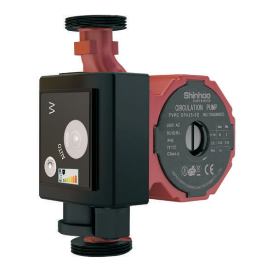
- Page 32 14. Features 14.1. Nameplate Instructions Descriptions Manufacturer Name Product Model Digit 1 to digit 6 indicates manufacturing date Product D igit 7 to digit 10 indicates serial number Minimum input power P1 Power Maximum input power P1 (Watt) Minimum current Current (Amp) Maximum current...
- Page 33 14.2. Model Instructions The model of motor pump is composed of capitalized Latin letters and Arabic numbers, which means: 01: Eight shifts+ night mode+ signal control Functional specification L: Grooving of base (for drainage of condensation) : Side mounting of junction box Product code C: Check valve installed at the pump outlet F: The connection type of pump body is flange connection,...
- Page 34 15. Technical Parameters and Installation Dimensions 15.1. Technical Parameters Power Supply Voltage 1×230V +6%/-10%,50/60Hz,PE Motor Protection The pump needs no external protection IP42 Degree of Protection Insulation Class Max. 95% Relative Humidity(RH) System Load Bearing 1.0 MPa Liquid Temperature Minimum Inlet Pressure ≤+ ℃...
-
Page 35: Installation Dimensions
15.2. Installation Dimensions Material of Dimension (mm) Pump Body Power Product Model Cast Plastic Copper SS B1 B2 H1 H2 G Iron ● GPA20-4PⅡ 1" ● ● ● 65/75 130/150 GPA20-4Ⅱ ● ● ● 65/75/90 130/150/180 1½" GPA25-4Ⅱ ● 2" GPA32-4Ⅱ... -
Page 36: Troubleshooting Schedule
16. Trouble-Shooting Schedule Warning Before conducting any maintenance and repair of the motor pump, ensure that power supply has been cut off and will not be connected accidentally. Symptom Control Panel Cause Corrective Action Replace the fuse Equipment fuse burned Indication The circuit breaker of Connect the circuit... - Page 37 Product Warranty Hefei Xinhu Canned Motor Pump Co., Ltd offers 12 months of quality warranty for its products since the date of sales, and is responsible for product malfunctions or damaged due to manufacturing and material defects. This warranty is valid only when the product is installed strictly in accordance with Xinhu installation and operation manual and certified operation practices.
Need help?
Do you have a question about the GPA-II Series and is the answer not in the manual?
Questions and answers