
Related Manuals for Shinhoo GPA-IV Series


Summary of Contents for Shinhoo GPA-IV Series
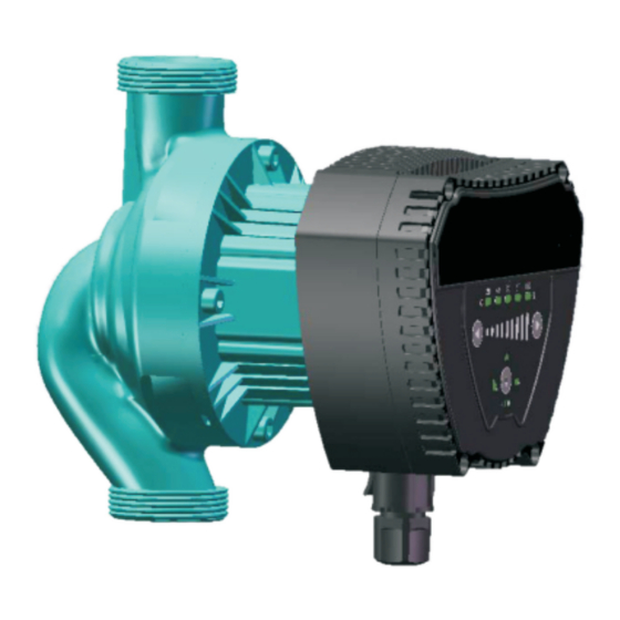
- Page 1 GPA-IV Series Energy-saving Pipeline Canned Motor Pump Installation and Operation Manual...
- Page 2 GPA- Notes: 01. Read the installation manual 11. Some models are not suitable for carefully before installation and drinking water. use. 12. The liquid may be high-temperature 02. The manufacturer will not be liable and high-pressure; therefore, the for any personal injur y, pump liq u i d i n t h e s y s te m m u s t be d a m a g e a n d o t h e r p ro p e r t y completely drained or the shut-off...
- Page 3 GPA-IV and abnormality of motor is detected, and contact your vendor or service center immediately. 19. If trouble cannot be addressed according to the manual, please close the valves on the inlet and outlet of the pump immediately, cut off power supply and contact your vendor or service center immediately.
- Page 4 GPA-IV General 2.1. GPA-Ⅳ series 2.2. Advantages circulation motor pump Easy installation and start-up is mainly u s e d i n · Provided with self-adaptive d o m e s t i c heating mode AUTO and hot water system. (Initial setting).
-
Page 5: Operating Conditions
GPA-IV 3. Operating Conditions 3.1. Ambient Temperature Ambient temperature: 0 ℃~ +40 ℃ 3.2. Relative humidity(RH): Max. humidity: 95% 3.3. Medium (liquid delivery) temperature Liquid delivery temperature: +2 ℃~ 110 ℃ To avoid condensation in control box and the stator, the temperature of liquid pumped by the motor pump must be always higher than ambient temperature. -
Page 6: Installation
GPA-IV 4. Installation 4.1Installation · When installing GPA -Ⅳseries circulating pump, the arrow on motor pump case indicates the flow direction of liquid through the pump. · When installing the motor pump in the pipeline, two supplied gaskets must be installed at the inlet and outlet. ·... - Page 7 GPA-IV 4.2Position of Junction Box 4.3Changing Position of Junction Box The junction box can be rotated in a step of 45° The procedure for changing the position of junction box are as follows: 1.Close the valves at the inlet and outlet and release the pressure; 2.Unscrew and remove the four socket head screws that fasten the pump body;...
- Page 8 GPA-IV Warning Pumping liquid may be high-temperature and high-pressure; therefore, t h e l i q u i d i n t h e s y s t e m must be completely drained or the valves on both sides of motor pump must be closed before removing the socket head screws.
-
Page 9: Electrical Connection
GPA-IV 5. Electrical Connection... - Page 10 GPA-IV Electrical connection and protection shall comply with local codes and norms. Warning The motor pump must be earthed The motor pump must be connected to an external power switch, and the minimum space between all the electrodes is 3mm. ·GPA -Ⅳseries circulating motor pump needs no protection from external motor.
-
Page 11: Control Panel
GPA-IV 6. Control Panel Controls on Control Panel Position Descriptions Flow during runtime Speed reduce button L i g h t i n g a r e a i n d i c a t i n g f o u r o p e r a t i n g m o d e Setting button showing pump operating mode Speed increase button... - Page 12 GPA-IV Lighting area Description Times to press the button AUTO(factory reset) Autoadaptation BL(1-9) Proportional pressure curve HD(1-9) Constant pressure curve HS(1-9) Constant speed curve 4Button for selecting motor pump settings By pressing the button once at 2 seconds interval, the motor pump setting mode will change once.
- Page 13 GPA-IV ·AUTO (Self Adaptive Mode) mode can adjust the performance of motor pump based on the actual heat demand of the system. As th e p e r f o r m a n c e is adjusted gradually, it is suggested, before changing motor pump setting, to maintain AUTO (Automatically Adaptive Mode) mode setting for at least one week.
- Page 14 GPA-IV 8.Bypass valve system installed between the Inlet pipeline and return pipeline 8.1Purposes of bypass valve Bypass valve The purpose of b y p a s s v a l v e : w h e n a l l t h e v a l v e s a n d / o r t e m p e r a t u r e - sensing valves of heat radiator in the floor heating l o o p a r e c l o s e d , i t c a n ensure that the heat from boiler can be distributed.
-
Page 15: Before Start-Up
GPA-IV When all valves are closed, the minimum flow r a t e m u s t b e g u a r a n t e e d. The setting of pump p o s i t i o n d e p e n d s o n t h e t y p e o f b y p a s s v a l v e , i . e. manual bypass valve or temperature-sensing bypass valve. - Page 16 GPA-IV 9.3Vent the heating system 10.Motor Pump Setting and Performance 10.1Relations between Motor Pump Setting and Performance Note:The red curre stands for constant speed gear (from 1 to 9),the shadow area of blue one is automatic gear,the green one is ratio gear (from 1 to 9),and the yellow one is constant pressure gear (from 1 to 9)
-
Page 17: Performance Curve
GPA-IV Pump Characteristics Setting Functions Curve AUTO function will automatically control the pump performance within the specified scope. Highest to AUTO ·adjust pump performance based on system scale; Lowest ·adjust pump performance based on load variance (Initial Proportional within a period of time; Setting)... - Page 18 GPA-IV ·Constant speed & AUTO mode performance curve GPAXX-6 Ⅳ Performance Chart(Constant Speed+auto Mode) GPAXX-8 Ⅳ Performance Chart(Constant Speed+auto Mode) GPAXX-10 Ⅳ Performance Chart(Constant Speed+auto Mode)
- Page 19 GPA-IV ·Constant pressure mode performance curve GPAXX-6 Ⅳ Performance Chart(Constant Pressure) GPAXX-8 Ⅳ Performance Chart(Constant Pressure) GPAXX-10 Ⅳ Performance Chart(Constant Pressure)
- Page 20 GPA-IV ·Proportional pressure performance curve GPAXX-6 Ⅳ Performance Chart(Bl Mode) GPAXX-8 Ⅳ Performance Chart(Bl Mode) GPAXX-10 Ⅳ Performance Chart(Bl Mode)
- Page 21 GPA-IV 12.Features 12.1Nameplate Instructions Descriptions Manufacturer Name Product Model Minimum mode minimum input power P1 Power Watt Maximum mode maximum input power P1 Current Minimum mode minimum current Maximum mode maximum current Maximum system load bearing (Mpa) Date Digit 1 to digit 6 indicates manufacturing date Digit seven to digit ten indicates serial number Frequency (Hz) Voltage (v)
- Page 22 GPA-IV 12.2Model Instructions the model of motor pump is composed of capitalized Latin letters and Arabic numbers, which means: Ⅳ C:check valve installed at the pump outlet F: the connection type of pump body is flange connection, threaded connection omitted Z: inlet and outlet direction of pump is axial inlet, radial inlet omitted P: plastic material of pump body...
-
Page 23: Technical Parameters
GPA-IV 13.Technical Parameters and Installation Dimensions 13.1Technical Parameters Power Supply Voltage 1x(220~240V)V,50/60Hz Motor Protection The pump needs no external protection Degree of Protection IP42 Insulation Class Relative Humidity(RH) Max95% 1.0 MPa System Load Bearing Minimum Inlet Pressure Liquid Temperature ≤+85℃ 0.005 Mpa Suction Port Pressure ≤+90℃... -
Page 24: Installation Dimensions
GPA-IV 13.2Installation Dimensions Material Dimension Power Model Castron Stainless steel Copper... - Page 25 GPA-IV Dimension Material Power Model Castron...
-
Page 26: Troubleshooting Schedule
GPA-IV 14.Trouble-Shooting Schedule Warning Before conducting any maintenance and repair of the motor pump,ensure that power supply has been cut off and will not be connected accidentally. Symptom Control Panel Cause Corrective Action Replace the fuse Equipment fuse burned Indication The circuit breaker of Connect the circuit current control or voltage control... -
Page 27: Product Warranty
GPA-IV Product Warranty Hefei Xinhu Canned Motor Pump Co., Ltd offers 12 months of quality warranty for its products since the date of sales, and is responsible for product malfunctions or damaged due to manufacturing and material defects. This warranty is valid only when the product is installed strictly in accordance with Xinhu installation and operation manual and certified operation practices.
Need help?
Do you have a question about the GPA-IV Series and is the answer not in the manual?
Questions and answers