TP-Link VIGI Quick Start Manual
Hide thumbs
Also See for VIGI:
- Installation manual (92 pages) ,
- Quick start manual (75 pages) ,
- Quick installation manual (2 pages)
Table of Contents
Advertisement
Quick Links
Quick Start Guide
Φ6 mm
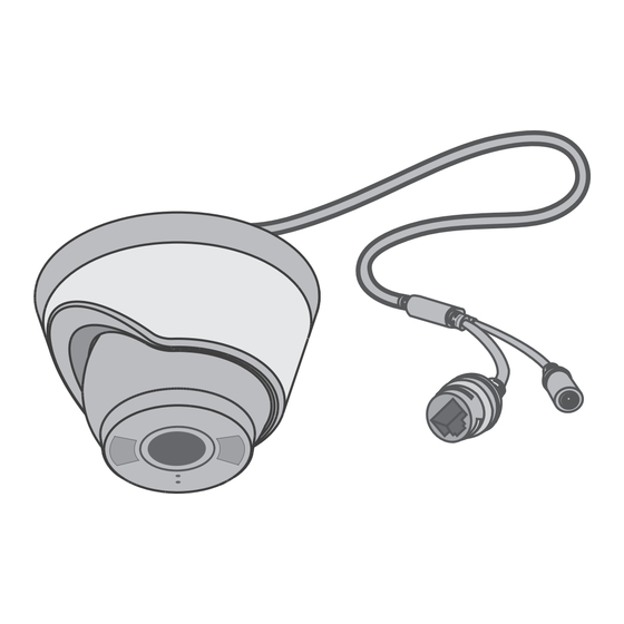
Network Camera
Power Adapter
Anchors & Screws
*Images may differ from actual products.
©2023 TP-Link 7106510179 REV2.0.0
1
Wall/Ceiling Mounting
Option 1: Cable through the wall/ceiling
1. Drill Holes
Stick the mounting template to the desired mounting place. Drill
3 screw holes and 1 cable hole according to the template.
2. Open the Camera Case
Align the notch of the camera body with any score on the camera
base, and use a screwdriver to gently pry open the camera case.
3. Secure the Camera
Route the cable through the wall/ceiling. Insert anchors into the holes,
use screws to affix the camera base, and attach the camera to it.
4. Adjust the Surveillance Angle
Adjust the surveillance angle as needed. Make sure the lens is
positioned above the IR LED for normal viewing.
Tilt: 0° to 85°
Rotate: 0° to 360°
Quick
Start
Guide
Φ3.5 mm
Mounting Template
Quick Start Guide
Appropriate drilling size (Φ)
When installing with anchors
Φ = 6 mm (15/64 in.)
Anchor
When installing with screws only
Φ = 3 mm (1/8 in.)
Cable Hole
(For the cable through wall/ceiling)
Notch of
camera body
Pan: 0° to 360°
Appearance
Camera Base
1
2
Press for 5 seconds to reset the
camera to factory settings.
microSD Card Slot
I
nsert a micro SD card for local
storage. Initialize the SD card via VIGI
app or other management tools before
recording videos.
4
Built-in Microphone
Option 2: Cable through the side outlet
1. Drill Holes
Stick the mounting template to the desired mounting place. Drill
3 screw holes according to the template.
2. Open the Camera Case
Align the notch of the camera body with any score on the camera
base, and use a screwdriver to gently pry open the camera case.
Notch of
the shell
3. Secure the Camera
Route the cable through the side outlet. Insert anchors into the holes,
use screws to affix the camera base, and attach the camera to it.
4. Adjust the Surveillance Angle
Adjust the surveillance angle as needed. Make sure the lens is
positioned above the IR LED for normal viewing.
Tilt: 0° to 85°
1
2
3
4
5
6
7
8
5
6
Status LED
White LED
IR LED
Speaker
7
9
10
Power Supply Interface
Appropriate drilling size (Φ)
When installing with anchors
Φ = 6 mm (15/64 in.)
Anchor
When installing with screws only
Φ = 3 mm (1/8 in.)
Notch of
camera body
Side Outlet
Pan: 0° to 360°
Rotate: 0° to 360°
9
10
Advertisement
Table of Contents

Related Manuals for TP-Link VIGI


Summary of Contents for TP-Link VIGI
- Page 1 Press for 5 seconds to reset the camera to factory settings. microSD Card Slot Quick Start Guide nsert a micro SD card for local storage. Initialize the SD card via VIGI app or other management tools before recording videos. Built-in Microphone Status LED...
- Page 2 • The power adapter must be used indoors. Make sure that the temperature of the power adapter is within 0-40°C. TP-Link hereby declares that the device is in compliance with the essential requirements and other relevant TP-Link hereby declares that the device is in compliance with the essential requirements and other relevant provisions of directives 2014/53/EU, 2009/125/EC, 2011/65/EU and (EU)2015/863.
Need help?
Do you have a question about the VIGI and is the answer not in the manual?
Questions and answers