Table of Contents
Advertisement
Quick Links
USA
SERVICE OFFICE
The Dometic Corp.
509 So. Poplar St.
LaGrange, IN 46761
CANADA
Dometic Dist.
866 Langs Dr.
Cambridge, Ontario
CANADA N3H 2N7
ALL INITIAL INSTALLATIONS MUST BE APPROVED BY THE SALES DEPT.
This unit must be serviced by an
authorized serviceman. Modifica-
tion of the appliance can be
extremely hazardous and could
lead to serious injury or death.
INSTALLATION & OPERATING
INSTRUCTIONS
Form No. 3106357.001 1/95
©1995 The Dometic Corp.
LaGrange, IN 46761
R
MODEL 630015.302 & 630015.402
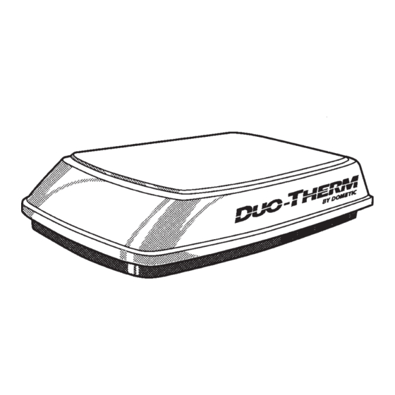
Roof-Top Heat Pump
THIS UNIT IS DESIGNED FOR OEM INSTALLATION
WARNING
637G
RECORD THIS INFORMATION FOR FUTURE REFERENCE
BEFORE INSTALLING THE UNIT:
Model Number
Serial Number
Date Purchased
Place of Purchase
Cet appareil doit être réparé seule-
ment par un réparateur autorisé.
Modification de l'appareil pourrait
être extrèmement dangereuse, et
pourrait causer mal ou mort.
630015.302
630015.402
® ®
CERTIFIED
LR 23565
1
AVIS
MODELS
Advertisement
Table of Contents

Subscribe to Our Youtube Channel
Summary of Contents for Dometic Duo-Therm 630015.302
- Page 1 être extrèmement dangereuse, et lead to serious injury or death. pourrait causer mal ou mort. MODELS INSTALLATION & OPERATING 630015.302 INSTRUCTIONS 630015.402 ® ® CERTIFIED LR 23565 Form No. 3106357.001 1/95 637G ©1995 The Dometic Corp. LaGrange, IN 46761...
-
Page 2: General Information
B. This air conditioner is designed for: B. The Dometic Corporation will not be liable for any 1) Installation on a recreational vehicle at the time the damages or injury incurred due to failure in following vehicle is manufactured. - Page 3 5-7/8" REAR 4-1/4" 21-1/2" NOTE: THE DOMETIC CORPORATION WILL NOT BE UNIT HELD LIABLE FOR ROOF STRUCTURAL OR CEIL- 14" x 14" Center L ine OPENING of Unit ING DAMAGE DUE TO IMPROPERLY INSULATED OR SEALED DUCTWORK.
- Page 4 THE ROOF AND THE CEILING. DISCONNECT ALL INSTALLATION POWER SUPPLIES AND THE POSITIVE (+) TERMI- NAL FROM THE SUPPLY BATTERY. FAILURE TO The Dometic Corporation recommends the basic configu- FOLLOW THIS INSTRUCTION MAY CREATE A ration shown below for installing this air conditioner sys- SHOCK HAZARD.
-
Page 5: Cable Installation
5. The 14" opening is part of the return air system THERMOSTAT AND CABLE of the air conditioner and must be finished in INSTALLATION accordance with NFPA Standard 501C Section 2.7. LOCATION 6. Route a copper 12 AWG with ground supply line The proper location of the thermostat is very impor- from fuse or circuit breaker box to the roof tant to insure that it will provide a comfortable RV... -
Page 6: Thermostat Wiring
C. THERMOSTAT WIRING 2) The outside temperature is above 40 degrees and Thermostat wiring for Dometic Bimetal thermostat: you wish to operate your furnace. Route the (10) conductor cable from the 14"x14" opening 3. For quick interior warm up. to the thermostat location. Leave enough cable within the 4. -
Page 7: Auxiliary Heat
The operator may choose the mode he desires to view The fan switch controls operation of the blower only by depressing the "MODE" switch. Each time the after the system switch is placed into the COOL or MODE switch is depressed, the display advances to HEAT PUMP position. - Page 8 3. Connect the white to white; black to black; and green to green or bare copper wire using the appropriate USE CARE IN LIFTING. THIS UNIT WEIGHS AP- sized twist wire connectors. Tape the twist wire con- PROXIMATELY ONE HUNDRED (100) POUNDS. nectors to the supply wiring to assure they do not vibrate off.
- Page 9 6) Start each mounting bolt through the ceiling tem- plate and up into the unit base pan by hand. EVENLY TIGHTEN MOUNTING BOLTS TO A EVENLY TIGHTEN MOUNTING BOLTS TO A EVENLY TIGHTEN MOUNTING BOLTS TO A EVENLY TIGHTEN MOUNTING BOLTS TO A EVENLY TIGHTEN MOUNTING BOLTS TO A TORQUE OF 40 TO 50 INCH POUNDS TORQUE OF 40 TO 50 INCH POUNDS...
- Page 10 C. INSTALLATION OF RETURN AIR COVER Thermostat Cable 1) Remove Return Air Grille from the Return Air Cover. 2) Place the Return Air Cover up to Ceiling Template. Return 3) Install Cover to Template with #8 x 3/8" blunt point Air Cover phillips head screws provided (6 required).
- Page 11 5. Measure the ceiling thickness: DISCHARGE DUCT & CEILING DISCHARGE DUCT & CEILING 10. DISCHARGE DUCT & CEILING DISCHARGE DUCT & CEILING DISCHARGE DUCT & CEILING a. If the distance is 2" to 3" remove the perforated TEMPLA TEMPLA TE INST TE INST ALLA ALLA...
-
Page 12: Connection Of Power Supply
8. Take the ceiling template and slide the lower duct CONNECTION OF POWER SUPPLY over the upper duct. 9. Hold the ceiling template with one hand and with the other, install the three 1/4" mounting bolts Disconnect ALL power before wire leads are con- through the template and into the base pan. -
Page 13: Wiring Diagram
WIRING DIAGRAM DIGITAL THERMOSTAT BI-METAL THERMOSTAT 12VDC POWER FURNACE SOURCE FURNACE 12 VDC WIRE NO T USED...


Need help?
Do you have a question about the Duo-Therm 630015.302 and is the answer not in the manual?
Questions and answers