Table of Contents
Advertisement
Quick Links
USA
SERVICE OFFICE
The Dometic Corp.
509 So. Poplar St.
LaGrange, IN 46761
CANADA
Dometic Dist.
866 Langs Dr.
Cambridge, Ontario
CANADA N3H 2N7
Improper installation, adjustment,
alteration, service or maintenance
can cause injury or property dam-
age. Refer to this manual. For as-
sistance or additional information
consult a qualified installer or ser-
vice agency.
INSTALLATION & OPERATING
INSTRUCTIONS
Form No. 3105532.018 8/94
©1994 The Dometic Corp.
LaGrange, IN 46761
®
SELF-CONTAINED HEAT PUMP
THIS UNIT IS DESIGNED FOR OEM INSTALLATION
ALL INITIAL INSTALLATIONS MUST BE APPROVED BY THE SALES DEPT.
WARNING
RECORD THIS INFORMATION FOR FUTURE REFERENCE
BEFORE INSTALLING THE UNIT:
Model Number
Serial Number
Date Purchased
Place of Purchase
FOR BASEMENT
PARK MODEL
ROTARY COMPRESSOR
SYSTEM MODELS
AVERTISSEMENT
Une mauvaise installation, de mauvais
réglages, modifications ou opérations
d'entretien peuvent endommager les
biens ou même blesser. Se reporter à
la notice. Pour obtenir de l'aide ou des
reseignements complémentaires,
consulter un installateur qualifié ou
une agence de service après-vente.
®
1
39325.502
SYSTEM
MODELS
39325.502
Advertisement
Table of Contents

Related Manuals for Dometic Duo-Therm 39325.502


Summary of Contents for Dometic Duo-Therm 39325.502
- Page 1 SYSTEM INSTALLATION & OPERATING MODELS INSTRUCTIONS 39325.502 ® Form No. 3105532.018 8/94 ©1994 The Dometic Corp. LaGrange, IN 46761...
-
Page 2: Table Of Contents
INDEX 4. Electrical Wiring ..............4 1. Specifications, General Information, Location ....... 5. Thermostat Mounting ............5 2. Outdoor Section ..............6. Thermostat Wiring ..............5 A. Free Area ............... 7. Ducts ..................7 B. Mounting ................ 8. Maintenance ................. 7 C. -
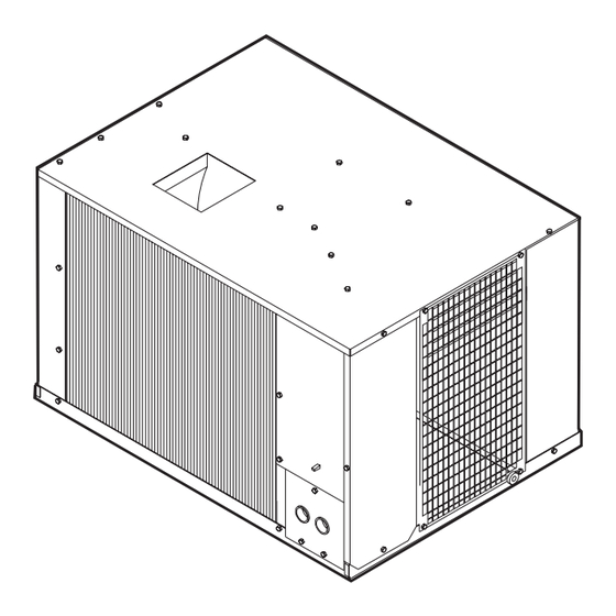
Page 3: Outdoor Section
OUTDOOR SECTION C. SERVICE ACCESS Be sure NOT to block the inlet or discharge air, or service The condenser coil is designed to have a fresh supply of access, when mounting. air. If skirting is installed, allow a 15" x 22" opening (330 square inches) for supply air and a 15"... -
Page 4: Electrical Wiring
NOTE: If the air conditioning unit is attached to the central B. EVAPORATOR SECTION-Line Voltage furnace, a damper must be installed at the furnace outlet 1. Remove electrical box cover. to prevent cold air from circulating through the furnace 2. Route supply wires through one of the bushings. heat exchanger. -
Page 5: Thermostat Mounting
THERMOSTAT MOUNTING AUTO: The fan cycles off and on with the compressor. Contact The Dometic Corporation for the proper thermo- ON: The fan will run continuously. The com- stat kit. The proper location of the thermostat is very pressor will turn off when the room temperature is important to ensure that it will provide a comfortable cool enough to satisfy the thermostat setting. - Page 6 NOTE: The auxiliary heat position is only used if: There are three display modes: ACTUAL, COOL and 1) You have a factory installed furnace operating HEAT. from the heat pump system thermostat. The operator may choose the mode he desires to view 2) The outside temperature is above 40 degrees and by depressing the "MODE"...
-
Page 7: Ducts
FAN SWITCH: The Fan Switch has four positions from C. When building around duct runs or placement of duct which to control the operation of the heat pump blower. material, DO NOT kink or crush tubing. If turns are The fan switch controls operation of the blower only required, maintain largest radii possible to decrease after the system switch is place into the COOL or pressure loss. -
Page 8: Wiring Diagram
WIRING DIAGRAM LINE SPLICE FACT ORY WIRING FIELD WIRING HIGH PTCR RELA Y BOARD COMP FURNACE TO THERMOSTAT CONNECTION...
Need help?
Do you have a question about the Duo-Therm 39325.502 and is the answer not in the manual?
Questions and answers