Table of Contents
Advertisement
Quick Links
USA
SERVICE OFFICE
Dometic Corporation
1120 North Main Street
Elkhart, IN, 46514
SERVICE CENTER &
DEALER LOCATIONS
Please Visit:
www.dometic.com
INSTALLATION & OPERATING
INSTRUCTIONS
REVISION C
Form No. 3315388.000 01/18
(French 3315389.000_C)
©2018 Dometic Corporation
LaGrange, IN 46761
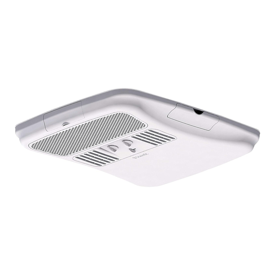
Description
Model
Heat Pump
650015, 650016
Read these instructions carefully. These
instructions MUST stay with this product.
RECORD THIS INFORMATION FOR FUTURE
REFERENCE:
Model Number
Serial Number
ADB Model Number
ADB Serial Number
Date Purchased
Roof Top Unit
Use With Air Distribution Box
Model
3314853.000
650015C75X
650015C85X
650016C75X
Control
Integral Mechanical
Model
Advertisement
Table of Contents

Related Manuals for Dometic 650015


Summary of Contents for Dometic 650015
- Page 1 Date Purchased Roof Top Unit Description Model Use With Air Distribution Box Model Control SERVICE OFFICE Heat Pump 650015, 650016 3314853.000 Integral Mechanical Dometic Corporation 1120 North Main Street Elkhart, IN, 46514 SERVICE CENTER & DEALER LOCATIONS Please Visit: www.dometic.com Model INSTALLATION &...
-
Page 2: Table Of Contents
This unit can be installed by one person with brief help from additional personnel. Use these instructions to ensure a properly installed, and properly functioning product. Dometic Corporation reserves the right to modify appearances and specifications without notice. TABLE OF CONTENTS INTRODUCTION ..................................2... -
Page 3: Important Safety Instructions
● This product MUST be [installed / serviced] by a qualified service technician. ● Do NOT modify this product in any way. Modifica- tion can be extremely hazardous. ● Do NOT add any devices or accessories to this product except those specifically authorized in writing by Dometic Corporation. -
Page 4: Specifications
For wire length over 24 ft., consult the National Electrical Code for proper sizing. ** Dometic Corporation gives GENERAL guidelines for generator requirements. These guidelines come from experiences people have had in actual applications. When sizing the generator, the total power usage of your RV must be considered. -
Page 5: Installation Instructions
RV parked on a 3-7/16″ level surface. See table below for maximum acceptable tilt. Model Roof Opening 21-1/8″ Number Tilt 650015 8° 650016 3-7/16″ After Location Has Been Selected: 2-7/8″ 6″ c. Check for obstructions in the area where unit will be installed. -
Page 6: Roof Preparation
INSTALLATION INSTRUCTIONS Roof Preparation FIG. 3 1. FIRE OR ELECTRICAL SHOCK HAZARD. Verify there are no obstacles inside RV’s roof and/or walls (wires, pipes, etc.). Shut OFF gas supply, disconnect 120 Vac power from RV and disconnect positive (+) 12 Vdc terminal Good Location Good-Rafters Do Not Cut Roof... -
Page 7: Installing Unit
INSTALLATION INSTRUCTIONS 3. Do NOT slide unit. Otherwise, FIG. 6 damage to gasket (on bottom of unit) may occur, and could cause a leak. Duct Divider Ceiling Lift and place the unit over the prepared open- Template ing using the gasket on the unit as a guide. See (FIG. - Page 8 See (FIG. 10). FIG. 12 Mounting Bolt FIG. 10 Cable Connector 120 Vac Unit Electrical Power Supply Cord Proper Orientation Mounting Bolt Of Cable Connector Mounting Bolt Pattern Table (See Fig. 13) Model Bolt Location 650015, 650016 B, C, F & G...
-
Page 9: Wiring System
INSTALLATION INSTRUCTIONS FIG. 13 FIG. 14 Junction Box Junction Cover Screw Box Cover d. Tape the connectors to the supply wire to as- g. Tighten mounting bolts to sure they don't vibrate loose. correct torque specifications. Overtighten- ing could damage unit’s base pan or ceiling e. - Page 10 INSTALLATION INSTRUCTIONS FIG. 16 FIG. 17 2 Sheet Hole In Ceiling Metal Screws Template ADB Hole Alignment Hole In ADB Cover 8 Wood Screws 4. Install front and rear doors. 5. Place filter in return air vent grille. It may already be installed on some units.
- Page 11 INSTALLATION INSTRUCTIONS FIG. 19 Slot In ADB Return Air Vent Grille 7. Install the control knobs into the ADB. See (FIG. 20). FIG. 20 Knob 8. The unit installation is now complete and is ready for operation. The power supply to the unit may now be turned on.
-
Page 12: Operating Instructions
OPERATING INSTRUCTIONS Controls Wait at least 2 minutes before restarting the compressor when it has been 1. The selector switch has ten positions includ- manually cycled off with either the selector ing "OFF". It controls the fan speeds, cooling switch or the temperature set lever. -
Page 13: Center Air Discharge
OPERATING INSTRUCTIONS Center Air Discharge 1. Slide lever to open and close. See (FIG. 22). FIG. 22 Slide To Open Or Close MAINTENANCE Air Filter 1. Periodically (a minimum of every 2 weeks of op- eration) remove the return air filter located be- hind the return air vent grille and wash it with soap and warm water, let dry and then reinstall. -
Page 14: General Information
For a more permanent solution to high heat gain, acces- a. Operation at low outdoor temperatures sories like Dometic outdoor patio and window awnings will causes low coil temperatures. This can result reduce heat gain by removing the direct sun. They also add in ice forming on the outdoor coil in certain a nice area to enjoy company during the cool of the evening. -
Page 15: Wiring Diagrams
WIRING DIAGRAMS Unit Wiring Diagram FIG. 23 PASSED COMPRESSOR REVERSING MOTOR VALVE DIELECTRIC GRN/YEL O.L. BLK OR PRP 9 PIN CONN HERM BLK OR WHT/PRP WHT/PNK OR RUN CAP AMBIENT RED OR PNK START SWITCH GRN/YEL PTCR (OPT) IN-LINE CONNECTOR 3310429.026 ADB Wiring Diagram FIG.
Need help?
Do you have a question about the 650015 and is the answer not in the manual?
Questions and answers