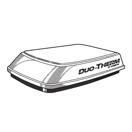
Dometic Duotherm Royale Penguin 600 Series Important Instructions Manual
Roof top air conditioner & heat pump used with part no. 3106476 or 3106575 air distribution box kit
Hide thumbs
Also See for Duotherm Royale Penguin 600 Series:
- Installation & operating instructions manual (14 pages) ,
- Installation instructions manual (17 pages)
Advertisement
USA
SERVICE OFFICE
The Dometic Corp.
509 So. Poplar St.
LaGrange, IN 46761
(219) 463-4858
CANADA
Dometic Dist.
866 Langs Dr.
Cambridge, Ontario
CANADA N3H 2N7
(519) 653-4390
This unit must be serviced by an
authorized serviceman. Modifica-
tion of the appliance can be
extremely hazardous and could
lead to serious injury or death.
INSTALLATION
INSTRUCTIONS
Form No. 3106529.005 6/95
©1995 The Dometic Corp.
LaGrange, IN 46761
®
ROOF TOP AIR CONDITIONER & HEAT PUMP
PART NO. 3106476 or 3106575
AIR DISTRIBUTION BOX KIT
WITH THE DUO-THERM COMFORT CONTROL CENTER™
PRE-WIRED FOR OPTIONAL HEAT PACKAGE (A/C ONLY)
637G
®
CERTIFIED
LR 23565
! DANGER
IMPORTANT INSTRUCTIONS
MUST STAY WITH UNIT
OWNER — READ CAREFULLY
RECORD THIS INFORMATION FOR FUTURE REFERENCE
BEFORE INSTALLING THE UNIT:
Model Number
Serial Number
Date Purchased
Place of Purchase
600 SERIES
USED WITH
®
Cet appareil doit être réparé seule-
ment par un réparateur autorisé.
Modification de l'appareil pourrait
être extrèmement dangereuse, et
pourrait causer mal ou mort.
1
®
R
! DANGER
MODELS
600312.321
600312.421
600315.321
600315.421
630035.421
Advertisement
Table of Contents

Summary of Contents for Dometic Duotherm Royale Penguin 600 Series
- Page 1 MODELS 600312.321 INSTALLATION 600312.421 INSTRUCTIONS 600315.321 600315.421 IMPORTANT INSTRUCTIONS 630035.421 MUST STAY WITH UNIT Form No. 3106529.005 6/95 OWNER — READ CAREFULLY ©1995 The Dometic Corp. LaGrange, IN 46761...
-
Page 2: General Information
For lengths over 24 ft., consult the National Electrical Code. The Dometic Corp. gives general guidelines for generator requirements. These guidelines come from experiences people have had in actual applications. When sizing the generator, the total power usage of your recreational vehicle must be considered. Also keep in mind generators lose power at high altitudes and from lack of maintenance. -
Page 3: Maintenance
3. MAINTENANCE D. FROST FORMATION ON COOLING COIL: Under A. AIR FILTERS: Periodically remove and clean the fil- certain conditions, frost may form on the evaporator ter/grille assemblies located in the air box. Remove the coil. If this should occur, inspect the filter and clean if assemblies by placing fingers on the long portion of dirty. - Page 4 Dometic A/C. If a furnace is to be connected, wires must be run from the furnace to the Dometic A/C. Read all C.
- Page 5 AIR CONDITIONER wire extends into the roof opening. (See Page 10, 15" Fig. 18) min. 3. DOMETIC COMFORT CONTROL CENTER™ & CABLE INSTALLATION A. LOCATION 1) If the system is to be used WITHOUT a Remote LEAVE ACCESS FOR Temperature Sensor, the proper location of the POWER SUPPLY WIRING Comfort Control Center™...
- Page 6 B. CONTROL CABLE INSTALLATION 2) Insert the telephone cable through the hole in the base plate and mount the plate to the wall with the A 4-conductor telephone cable must be routed from the two screws provided. Check the alignment to en- roof opening to the Comfort Control Center™...
- Page 7 5. DISCHARGE DUCT & CEILING FIG. 10 TEMPLATE INSTALLATION A. Remove the air box and mounting hardware from their carton. The upper duct is shipped inside the lower duct which is part of the ceiling template. FIG. 8 F. Measure the ceiling thickness: 1) If the distance is 2"...
- Page 8 5) If the A/C is a Heat Pump model (630035), route FIG. 12 the Ambient Air Sensor Cable, already installed in the base model, through the grommet in the Elec- tronic Control Kit and attach it to the connector that matches its color.
-
Page 9: Air Box Installation
SYSTEM CHECKOUT & 7) SYSTEM CONFIGURATION: If all features are functioning, perform the following configuration CONFIGURATION procedure: Now that the system is installed, it is necessary to check all a) Simultaneously depress UP and DN operations and then configure the electronics. pushbuttons on the Comfort Control Center™... - Page 10 FIG. 17 REAR ROOF MOUNT AIR CONDITIONER ASSEMBLY DISCHARGE AIR RETURN AIR OPENING RATING PLATE & SERIAL NO. NEOPRENE RUBBER GASKET FRONT UPPER DISCHARGE AIR DUCT ROOF LINE WALL THERMOSTAT CABLE ROOF REINFORCEMENT MEMBER POWER SUPPLY LINE 14-1/4" X 14-1/4" OPENING FRAMING, RETURN AIR DUCT LOWER DISCHARGE AIR DUCT ELECTRONIC CONTROL BOX...
-
Page 11: Air Conditioner
WIRING DIAGRAMS AIR CONDITIONER ELECTRONIC CONTROL KIT HEAT PUMP...


Need help?
Do you have a question about the Duotherm Royale Penguin 600 Series and is the answer not in the manual?
Questions and answers