Table of Contents
Advertisement
Quick Links
EVB-I94124ADI
®
®
ARM
Cortex
-M4
32-bit Microcontroller
EVB-I94124ADI
User Manual
I94100 Series
The information described in this document is the exclusive intellectual property of
Nuvoton Technology Corporation and shall not be reproduced without permission from Nuvoton.
Nuvoton is providing this document only for reference purposes of NuMicro microcontroller based system
design. Nuvoton assumes no responsibility for errors or omissions.
All data and specifications are subject to change without notice.
For additional information or questions, please contact: Nuvoton Technology Corporation.
www.nuvoton.com
August 30, 2017
Page 1 of 19
Rev 1.0
Advertisement
Table of Contents

Related Manuals for Nuvoton I94100 Series


Summary of Contents for Nuvoton I94100 Series
- Page 1 The information described in this document is the exclusive intellectual property of Nuvoton Technology Corporation and shall not be reproduced without permission from Nuvoton. Nuvoton is providing this document only for reference purposes of NuMicro microcontroller based system design. Nuvoton assumes no responsibility for errors or omissions.
-
Page 2: Table Of Contents
EVB-I94124ADI Table of Contents Overview ..................... 5 Introduction to EVB-I91240ADI Board .............. 5 I94100 Series MCU Features ................ 5 EVB-I94124ADI Board Features ..............6 EVB-I94124ADI Board Overview ..............7 Front View ....................7 Rear View ....................8 Power Supply ................... 9 Pin Assignment for Extended Connectors ............ - Page 3 EVB-I94124ADI List of Figures Figure 1-1 EVB-I94124ADI Board ....................5 Figure 2-1 Front View of EVB-I94124ADI Board ................7 Figure 2-2 Rear View of EVB-I94124ADI Board ................8 Figure 2-3 Power Supply Concept ....................9 Figure 2-4 I94124ADI Extended Connectors ................. 10 Figure 2-5 Front Placement ......................
- Page 4 EVB-I94124ADI List of Tables Table 2-1 Extended Connector JP7 Interface with I94124ADI GPIO ..........11 Table 2-2 Extended Connector JP5 Interface with I94124ADI GPIO ..........11 Table 2-3 Extended Connector JP4 Interface with I94124ADI GPIO ..........12 Table 2-4 Extended Connector JP6 Interface with I94124ADI GPIO ..........12 August 30, 2017 Page 4 of 19 Rev 1.0...
-
Page 5: Overview
EVB-I94124ADI OVERVIEW EVB-I94124ADI is the specific development tool for I94100 series. User can use EVB-I94124ADI to develop and verify the application program easily. EVB-I94124ADI includes two portions. One is I94124ADI evaluation board and the other is Debug Adaptor (Nu-Link-Me). Thus, users do not need other additional ICE or debug equipment. -
Page 6: Evb-I94124Adi Board Features
EVB-I94124ADI UART USB 1.1 Full-Speed Device DMIC DPWM EVB-I94124ADI Board Features On board Nu-Link-Me ICE Bridge (Mass storage as USB Disk drive) for drag and drop programming I94124 extended interface connectors ... -
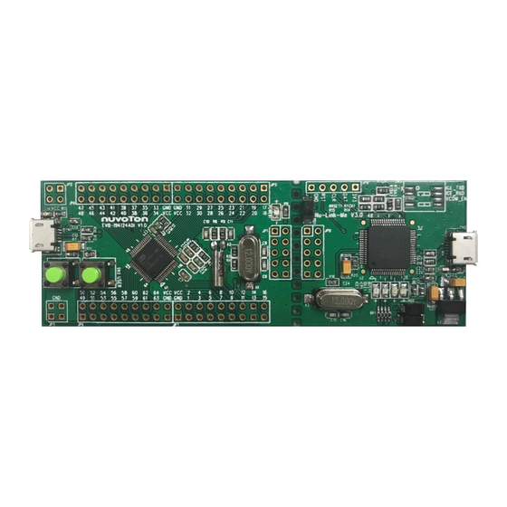
Page 7: Evb-I94124Adi Board Overview
EVB-I94124ADI EVB-I94124ADI BOARD OVERVIEW Front View Figure 2-1 shows the main components and connectors from the front side of EVB-I94124ADI board. The following lists components and connectors from the front view: Target Chip: I94124ADI (U1) Nu-Link-Me ICE Bridge: ICE Controller NUC12SRE3DE (U2), USB connector (CN2) to PC Host ... -
Page 8: Rear View
EVB-I94124ADI Rear View Figure 2-2 shows the rear side of EVB-I94124ADI board. Figure 2-2 Rear View of EVB-I94124ADI Board August 30, 2017 Page 8 of 19 Rev 1.0... -
Page 9: Power Supply
EVB-I94124ADI Power Supply The EVB-I94124ADI supplied by an external 5 Volt DC power supply connected to Micro USB connectors (CN1 and CN2) or 1.6 Volt to 3.6 Volt DC power supply connected to Pin Header (JP2). On-board reverse current protection diodes will ensure safe operation in case power is provided through both USB connectors at the same time. -
Page 10: Figure 2-4 I94124Adi Extended Connectors
EVB-I94124ADI Figure 2-4 I94124ADI Extended Connectors August 30, 2017 Page 10 of 19 Rev 1.0... -
Page 11: Table 2-1 Extended Connector Jp7 Interface With I94124Adi Gpio
EVB-I94124ADI Table 2-1 Extended Connector JP7 Interface with I94124ADI GPIO I94124ADI I94124ADI Header Header Pin No. Pin Name Pin No Pin Name JP7.1 JP7.2 JP7.3 PB.0 JP7.4 PB.1 JP7.5 PB.2 JP7.6 PB.3 JP7.7 PB.4 JP7.8 nRESET JP7.9 PB.5 JP7.10 PB.6 JP7.11 PB.7 JP7.12... -
Page 12: Table 2-3 Extended Connector Jp4 Interface With I94124Adi Gpio
EVB-I94124ADI Table 2-3 Extended Connector JP4 Interface with I94124ADI GPIO I94124ADI I94124ADI Header Header Pin No. Pin Name Pin No Pin Name JP4.1 JP4.2 JP4.3 PB.15 JP4.4 PB.14 JP4.5 PB.13 JP4.6 PD.0 JP4.7 PD.1 JP4.8 PD.2 JP4.9 PD.3 JP4.10 PD.4 JP4.11 PD.5 JP4.12... -
Page 13: System Configuration
EVB-I94124ADI System Configuration 2.5.1 5V Power Source CN2: USB connector in Nu-Link-Me to program code and supplies 5V power from PC Host. CN1: USB 1.1 device connector on EVB-I94124ADI board to supply 5V power from PC Host. Power Component Comment Source... -
Page 14: Power Connectors
EVB-I94124ADI 2.5.7 Power Connectors JP2: VCC (Range: 1.6V to 3.6V) connectors on the EVB-I94124ADI board. JP3: GND connectors on the EVB-I94124ADI board. 2.5.8 Clock Source X1: 12 MHz crystal. (By removing resistor R4 and R5, the crystal can be disconnected from PB.5 and PB.6) ... -
Page 15: Components Placement
EVB-I94124ADI Components Placement Figure 2-5 and Figure 2-6 show the front and rear placement of EVB-I94124ADI board. Figure 2-5 Front Placement Figure 2-6 Rear Placement August 30, 2017 Page 15 of 19 Rev 1.0... -
Page 16: Evb-I94124Adi Schematics
PA11 PA10 1uF/6.3V R0603 C0603 Shield nRESET PA15 R0603 3300pF R0603 C0603 Nuvoton Title I94124ADI MCU Size Document Number EVB-I94124ADI Date: Wednesday , August 30, 2017 Sheet Figure 3-1 I94124ADI Circuit August 30, 2017 Page 16 of 19 Rev 1.0... -
Page 17: Nu-Link-Me
LED0805 BUSY 1 BUSY 1 3V3_ICE GREEN 3V3_ICE LED0805 ICE_VBUS SS24A R0603 3V3_ICE DEBUG_DAT DEBUG_CLK RB060L DEBUG_RST DEBUG_RST Nuvoton 10uF/10V 10uF/10V USB_VBUS SS24A TANT-A TANT-A Title 10uF/10V NULINK-ME TANT-A RB060L Size Document Number EVB-I94124ADI Date: Wednesday , August 30, 2017... -
Page 18: Revision History
EVB-I94124ADI REVISION HISTORY Date Revision Description 2017.08.30 Initially issued. August 30, 2017 Page 18 of 19 Rev 1.0... - Page 19 EVB-I94124ADI Important Notice Nuvoton Products are neither intended nor warranted for usage in systems or equipment, any malfunction or failure of which may cause loss of human life, bodily injury or severe property damage. Such applications are deemed, “Insecure Usage”.
Need help?
Do you have a question about the I94100 Series and is the answer not in the manual?
Questions and answers