Table of Contents
Advertisement
Quick Links
NUC505
®
ARM Cortex
-M
32-bit Microcontroller
NuMicro™ Family
NuTiny-SDK-NUC505
User Manual
The information described in this document is the exclusive intellectual property of
Nuvoton Technology Corporation and shall not be reproduced without permission from Nuvoton.
Nuvoton is providing this document only for reference purposes of NuMicro microcontroller based system
design. Nuvoton assumes no responsibility for errors or omissions.
All data and specifications are subject to change without notice.
For additional information or questions, please contact: Nuvoton Technology Corporation.
www.nuvoton.com
Jun. 11, 2018
Page 1 of 26
Rev 1.03
Advertisement
Table of Contents

Related Manuals for Nuvoton NuMicro NuTiny-SDK-NUC505


Summary of Contents for Nuvoton NuMicro NuTiny-SDK-NUC505
- Page 1 The information described in this document is the exclusive intellectual property of Nuvoton Technology Corporation and shall not be reproduced without permission from Nuvoton. Nuvoton is providing this document only for reference purposes of NuMicro microcontroller based system design. Nuvoton assumes no responsibility for errors or omissions.
-
Page 2: Table Of Contents
How to Start NuTiny-SDK-NUC505 on the Keil μVision IDE Software Download and Install ..........10 ® Keil uVision Nuvoton Nu-Link Driver Download and Install ........... 10 Hardware Setup ..................10 Smpl_NuTiny-NUC505 Example Program ............11 NuTiny-EVB-NUC505 Schematic .............. 13 NUC505 ....................13 RESET and RTC_WAKEUP Button ............... - Page 3 NUC505 Others PCB Design Guideline for USB 2.0 ............... 18 4.6.4 Power ....................19 LED ..................... 20 Micro SD Card Slot ................... 21 Audio Line In, Headphone Out and MIC ............22 4.10 Audio Line In ....................22 4.10.1 Audio Headphone Out ..................23 4.10.2 Microphone In ....................
-
Page 4: Overview
NUC505 OVERVIEW NuTiny-SDK-NUC505 is the specific development tool for NuMicro NUC505 series. Users can use NuTiny-SDK-NUC505 to develop and verify the application program easily. NuTiny-SDK-NUC505 includes two portions. One is NuTiny-EVB-NUC505 and the other is Nu- Link-Me. NuTiny-EVB-NUC505 is the evaluation board and Nu-Link-Me is its Debug Adaptor. Thus, users do not need other additional ICE or debug equipment. -
Page 5: Nutiny-Sdk-Nuc505 Introduction
To use Nu-Link-Me Debug adaptor with IAR or Keil, please refer to “Nuvoton NuMicro™ IAR ICE driver user manual “or Nuvoton NuMicro™ Keil ICE driver user manual” in detail. These two documents will be stored in the local hard disk when the user installs each driver. -
Page 6: Nutiny -Sdk-Nuc505 Jumper Description
NUC505 NuTiny -SDK-NUC505 Jumper Description NuTiny-SDK-NUC505 is the specific development tool for NuMicro NUC505 series. Users can use NuTiny-SDK-NUC505 to develop and verify the application program easily. NuTiny-SDK-NUC505 includes two portions. One is NuTiny-EVB-NUC505 and the other is Nu- Link-Me. NuTiny-EVB-NUC505 is the evaluation board and Nu-Link-Me is its Debug Adaptor. Thus, users do not need other additional ICE or debug equipment. -
Page 7: Debug Connector
NUC505 2.1.2 Debug Connector CON5: Connector in target board (NuTiny-EVB-NUC505) for connecting with Nuvoton ICE adaptor (Nu-Link-Me) ICON1: Connector in ICE adaptor (Nu-Link-Me) for connecting with a target board (for example NuTiny-EVB-NUC505) 2.1.3 ICE USB Connector ICON2: Mini USB Connector in Nu-Link-Me connected to a PC USB port 2.1.4... -
Page 8: Pin Assignment For Extended Connector
NUC505 Pin Assignment for Extended Connector NuTiny-EVB-NUC505 provides NUC505YO13Y on board and the extended connector for QFN- 88 pin. Table 2-1 is the pin assignment for NUC505YO13Y Pin No Pin Name Pin No Pin Name Pin No Pin Name Pin No Pin Name RESETn RTC_VDD33... -
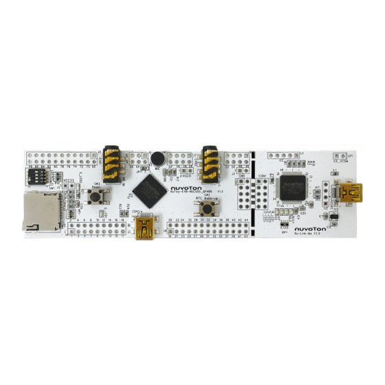
Page 9: Nutiny-Sdk-Nuc505 Pcb Placement
NUC505 NuTiny-SDK-NUC505 PCB Placement Users can refer to Figure 2-2 for the NuTiny-SDK-NUC505 PCB placement. Figure 2-2 NuTiny-SDK-NUC505 PCB Placement Jun. 11, 2018 Page 9 of 26 Rev 1.03... -
Page 10: How To Start Nutiny-Sdk-Nuc505 On The Keil Μvision
IDE Software Download and Install ® μ Please visit the Keil company website (http://www.keil.com) to download the Keil Vision and install the RVMDK Nuvoton Nu-Link Driver Download and Install ™ Please visit the Nuvoton company NuMicro website (http://www.nuvoton.com/NuMicro) to ™ ®... -
Page 11: Smpl_Nutiny-Nuc505 Example Program
Boot from Internal SPI Flash Smpl_NuTiny-NUC505 Example Program This example demonstrates the ease of downloading and debugging an application on a NuTiny- SDK-NUC505 board. It can be found on Figure 3-2 list directory and downloaded from Nuvoton ™ NuMicro website. - Page 12 NUC505 To use this example: The LED will toggle on the NuTiny-EVB-NUC505 board. Start μVision ® Start debug mode Using the debugger commands, you may: Project-Open Open the Smpl_NuTiny.uvproj project file Review variables in the watch window ...
-
Page 13: Nutiny-Evb-Nuc505 Schematic
NUC505 NUTINY-EVB-NUC505 SCHEMATIC NUC505 Jun. 11, 2018 Page 13 of 26 Rev 1.03... -
Page 14: Reset And Rtc_Wakeup Button
NUC505 RESET and RTC_WAKEUP Button The reset need R 1k ohm and C 10uf for reset circuit. Crystal 4.3.1 HXT:High Speed Crystal (12 MHz) For C16 and C17 is recommended to use high-quality ceramic capacitors in the 5pF~20pF range, designed for high-frequency applications and selected to meet the requirements of the crystal or resonator. -
Page 15: Ice Interface
NUC505 ICE Interface For ICE Mode debug or ICP Mode download code to flash Jun. 11, 2018 Page 15 of 26 Rev 1.03... -
Page 16: Boot Select
NUC505 Boot Select The power-on setting is used to configure the chip to enter the specified state when the chip is powered up or reset. Since each pin of power on setting has an internal pulled-up resistor when in reset period. If the application needs to set the configuration to “0”, the proper pull-down resistor of 10K-ohm must be added for the corresponding configuration pins. -
Page 17: Usb 2.0 High Speed Device
NUC505 USB 2.0 High Speed Device The layout rule needs to take USB 2.0 high speed device. 4.6.1 PCB Layer Stack-up For a USB 2.0 high-speed design, recommend to use at least a four-layer PCB for best signal characteristics. The majority of signal traces should run on a single layer, next to this layer should be the GND plane, which is solid with no cuts. -
Page 18: Signal Trace For D+ And D
NUC505 4.6.3 Signal Trace for D+ and D- To avoid the trace effect signal for the eye diagram, the trace length should be almost the same of D+ and D-. Then, the characteristic impedance should be a symmetrical path for the differential end of the USB port. -
Page 19: Power
NUC505 Power Note:The 0 ohm resister can short in user application. Jun. 11, 2018 Page 19 of 26 Rev 1.03... -
Page 20: Led
NUC505 The G_LED2 shows when VDD33 has been supplied. GPIO PC3 can control G_LED1 to toggle LED. Jun. 11, 2018 Page 20 of 26 Rev 1.03... -
Page 21: Micro Sd Card Slot
NUC505 Micro SD Card Slot CON4 is micro SD Card Slot, it is access by SHDC mode, Max clock can run 50 MHz Jun. 11, 2018 Page 21 of 26 Rev 1.03... -
Page 22: Audio Line In, Headphone Out And Mic
NUC505 4.10 Audio Line In, Headphone Out and MIC For audio application, the headphone out for audio out, JP1 is bais voltage select for MIC(2-3 short) or line in(1-2 short). 4.10.1 Audio Line In The device provides left and right channel line-in inputs. The inputs are high impedance, low capacitance AC coupled. -
Page 23: Audio Headphone Out
NUC505 4.10.2 Audio Headphone Out This device provides two low impedance line outputs (LHPOUT and RHPOUT), suitable for driving typical line loads of impedance 10k and capacitance 50pF. The recommended external components are shown in the figure below: Jun. 11, 2018 Page 23 of 26 Rev 1.03... -
Page 24: Microphone In
NUC505 4.10.3 Microphone In The device supports 2 types of Microphone inputs that can be either differential or single- ended, The differential mode as shown below. Jun. 11, 2018 Page 24 of 26 Rev 1.03... -
Page 25: Revision History
NUC505 REVISION HISTORY Date Revision Description 2015.2.8 1.00 Initially issued. 2015.12.1 1.01 Change the schematic, placement and layout. 2017. 11.11 1.02 Change the schematic, placement and layout. 2018.6.11 1.03 Fix in typo section 4.2. Jun. 11, 2018 Page 25 of 26 Rev 1.03... - Page 26 NUC505 Important Notice Nuvoton Products are neither intended nor warranted for usage in systems or equipment, any malfunction or failure of which may cause loss of human life, bodily injury or severe property damage. Such applications are deemed, “Insecure Usage”.
Need help?
Do you have a question about the NuMicro NuTiny-SDK-NUC505 and is the answer not in the manual?
Questions and answers