Table of Contents
Advertisement
Advertisement
Chapters
Table of Contents

Related Manuals for Nuvoton CODEC 8812 series


Summary of Contents for Nuvoton CODEC 8812 series
- Page 1 CODEC Motherboard Nuvoton Audio Codec Motherboard Evaluation Board User’s Guide (For Nuvoton CODEC series: 8812, 8814, 8810, 88C10, 8811, 8820, 8822, 8822L, 88C22, 8401, 8402, 8501, and 8502.) CODEC Motherboard Manual Version 1.3 Page 1 of 66 April 12, 2016...
- Page 2 This system is a combination of hardware and software that enables fast and detailed evaluation of Nuvoton audio products. The hardware consists of a base evaluation board and a daughter card which contains the specific audio product to be evaluated. The daughter card system enables the use of the same base motherboard hardware and software to evaluate many different Nuvoton audio products.
-
Page 3: Table Of Contents
CODEC Motherboard TABLE OF CONTENTS Hardware Overview ....................6 Software Installation and Set-Up ................7 PC Configuration ..................... 8 Running the GUI Application ................... 9 Getting Started Using the GUI Application ............. 10 5.1. DEMO Panel Status Indicators ..............10 5.1.1. - Page 4 CODEC Motherboard 6.8.2.1. REFIMP ..................... 29 6.8.2.2. FS (Frame Sync) ................30 6.8.2.3. Clock Prescalers ................30 6.8.2.4. Config PLL ..................30 6.8.3. Digital Audio Control ................31 6.8.3.1. Clock Generation Control ..............31 6.8.3.1.1. CLKIOEN Master Mode ............... 31 6.8.3.1.2.
- Page 5 CODEC Motherboard 8.4. Digital Audio Using the NAU8822 ..............47 8.4.1. NAU8822 Master Clock Requirement ............. 47 8.4.2. Master Clock Selection ................47 8.4.3. Frame Sync (Sample Rate Clock) ............47 8.4.4. Bit Clock (BLCK) ..................47 8.5. Digital Audio Input ..................48 8.5.1.
-
Page 6: Hardware Overview
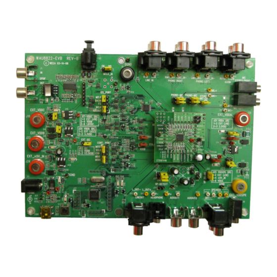
CODEC Motherboard 1 Hardware Overview All instructions in this guide require some familiarity with the physical layout of the motherboard and daughter cards. This information is introduced as needed, so it is not necessary at first to memorize or understand the complete layout and functions of the hardware. There are various daughter card can be used for the same motherboard. -
Page 7: Software Installation And Set-Up
If the installation software has been downloaded, the installer program will request a Username and Password to complete the installation procedure. Normally, these will have been provided in advance by a Nuvoton sales representative. Using a downloaded version of the software will insure having the most recently released version of the program. -
Page 8: Pc Configuration
The Nuvoton EVB is registered as an "Audio Device." It is possible other audio devices attached to the PC may have the same or similar name. The Nuvoton EVB can be identified in this case by unplugging/replugging into the PC to see which item is changed in the list of audio devices. -
Page 9: Running The Gui Application
The program will always be available under the Run option in the Start Menu. The application name will always start with the word "Nuvoton.” The application may be started with or without the motherboard USB hardware attached. If the motherboard is not attached, the application will run in a "software demo"... -
Page 10: Getting Started Using The Gui Application
CODEC Motherboard Getting Started Using the GUI Application After making the selection on the start-up screen to select the audio device to be evaluated, the GUI Application will open to the Demo Panel screen. All panels are structured similarly and include the Main Menu Bar, Control Tabs, and Status Indicators. -
Page 11: Power Up Indicator
CODEC Motherboard 5.1.2 Power Up Indicator The middle status indicator is the Power Up Indicator. This will be Green after the software has powered up all elements on the motherboard necessary to interoperate with the daughter card. If the indicator is white, then the motherboard and communications between the motherboard and daughter card have not been set up, and no interaction with the daughter card is possible. -
Page 12: The Control Tabs
CODEC Motherboard The Control Tabs All of the main features and many options are selected by choosing one of the Control Tabs. This is the horizontal menu list immediately below the Main Menu. After the user selects the device, the application automatically opens into the Control Tab for the Demo Panel. It is best to first work with the Demo Panel to begin learning how to use this application and the other Control Tabs. -
Page 13: Step 1: Configure
CODEC Motherboard 6.1.1 Step 1: Choose Settings The Choose Settings selection enables selection of the input, as well as the entire path for audio from the selected input, through all of the device options, and then to the output. The path descriptions are listed in an abbreviated form to fit within the GUI display. -
Page 14: Demo Example For Nau8822
CODEC Motherboard Demo Example for NAU8822 In this example, the goal is to pass audio from the left and right auxiliary inputs, into the ADC, from the ADC into the DAC, and then output to the headphones. This is accomplished by the following three steps: Choose: "L/R AUXIN =>... -
Page 15: Description Of Special Icons In Path View
CODEC Motherboard This panel is intended to be used after a full set of settings has already been loaded into the device. This panel is difficult or impossible to use without having done this first. The main reason for this is that power control features are in the "off" condition, and these are not all directly available on the Path View. -
Page 16: Device Control Panel
CODEC Motherboard Device Control Panel This panel modifies the basic configuration of both the motherboard and the audio device under test. In general, these features are for advanced users. Except for the "Initialize Board," "Initialize Device," and "Device Control" radio buttons, other settings in this panel should not be changed without a good understanding of the underlying functions. -
Page 17: Device Settings
CODEC Motherboard 7.2.1 Device Settings This changes the 5-volt or 3-volt settings of the NAU8822 outputs to match the actual voltage supplied on the VDDSPK pin. Management of the power options is explained in other sections of this document. IMPORTANT: These settings should NOT be changed unless work is being done to change the internal or external VDDSPK voltage. -
Page 18: Board Settings
CODEC Motherboard 7.2.2 Board Settings These settings change the basic configuration of the motherboard communications with the device on the daughter card. These can affect the control bus mode, the I2S audio data stream, and also select external connectors as alternative sources and sinks for these signals. IMPORTANT: Changes to this portion of the panel do NOT become effective until pushing the "Config Board"... -
Page 19: External Control
CODEC Motherboard External Control In addition to the built-in interfaces, an external command interface control can be selected. In this case, control to and from the daughter card is via the CONT. PORT, Connector J24. Bi- directional level shifters are used to connect the daughter card to this port instead of to the internal port provided on the motherboard. -
Page 20: Digital Audio Master
CODEC Motherboard 7.5.5 Digital Audio Master This control is for when I2S audio is streamed from the SPDIF controller included on the motherboard. Bi-directional level shifters are selected by this option to connect the daughter card to the SPDIF controller, instead of to the USB I2S port also provided on the motherboard. When selecting SPDIF audio in the Demo Panel, this selection is made automatically. -
Page 21: I2S Slave
CODEC Motherboard 7.5.6 I2S Slave The motherboard can be configured as the I2S Master or I2S Slave, but not both at the same time. In most applications, the motherboard will be the I2S Master. This section controls options for the audio signal source in I2S slave mode. 7.5.7 Audio Precision Slave Mode This control is for when I2S audio is streamed to an external slave device connected to the I2S_PORT, Connector J15. -
Page 22: Power Management
CODEC Motherboard Power Management This panel of controls gives direct access to the various power management bits available in the NAU8822 device. Control of these bits is normally automatic. These bit controls are made available here for convenient manipulation and evaluation of the power control features. The function of each of these control bits is explained in detail in the NAU8822 device Design Guide documentation. -
Page 23: Input Path Control Panel
CODEC Motherboard Input Path Control Panel This Control Tab gives access to the various controls and settings for the analog audio input routing, power management, and gain blocks up to, but not including, the ADC converters. Control of these bits is normally automatic when using the Demo Panel. These bit controls are provided here for convenient manipulation and evaluation of the input path features and settings. -
Page 24: Adc/Filtering Control Panel
CODEC Motherboard 10 ADC/Filtering Control Panel This Control Tab gives access to the various controls and settings in the ADC converter blocks. Controls are also included here for the digital high pass filter, digital notch filter, and gain options associated with the ADC function. Control of these bits is normally automatic when using the Demo Panel. -
Page 25: Equalizer Control Panel
CODEC Motherboard 11 Equalizer Control Panel This Control Tab gives access to the various controls and settings for the Equalizer and 3-D Audio digital signal processing blocks. This pair of functions may be applied to either the ADC digital outputs, or to the DAC digital inputs, but not to both paths at the same time. These features are explained in detail in the NAU8822 device Design Guide documentation. -
Page 26: Input Limiter And Alc Control Panel
CODEC Motherboard 12 Input Limiter and ALC Control Panel This Control Tab gives access to the various controls and settings for the Input Limiter and ALC signal control blocks. The operation of each of these functions is explained in detail in the NAU8822 device Design Guide documentation. -
Page 27: Dac/Pll/Digital Audio Control Panel
CODEC Motherboard 13 DAC/PLL/Digital Audio Control Panel This Control Tab manages three major functional groups: control of the DACs themselves, management of the PLL and voltage reference that support the DACs, and miscellaneous functions also related to operation of the DACs. The operation of each of these functions is explained in detail in the NAU8822 device Design Guide documentation. -
Page 28: Dac Control
CODEC Motherboard DAC Control 13.1 As mentioned in the heading of this section, the details of all of the functions and bits are described in detail in the NAU8822 Design Guide and appendices. The bit names match this documentation, and using a text string search in the Design Guide is a good method to quickly locate specific information about a specific control bit function. -
Page 29: Pll Control
CODEC Motherboard PLL Control 13.3 The PLL is one of the most powerful and also most difficult to understand features of NAU8822 devices. It is important to understand carefully the detailed information regarding the PLL that is included in the NAU8822 Design Guide. As mentioned in the heading of this section, the details of all of the functions and bits are described in detail in the NAU8822 design guide and appendices. -
Page 30: Fs (Frame Sync)
CODEC Motherboard FS (Frame Sync) 13.5 This is the pin name and bit name for the Frame Sync function. The FS rate is normally the same as actual sampling rate intended for the device. However, FS is simply the rate at which samples are transmitted over the I2S or PCM digital audio bus. -
Page 31: Digital Audio Control
CODEC Motherboard Digital Audio Control 13.8 Figure 17: DAC/PLL/DIGITAL AUDIO PANEL – DIGITAL AUDIO CONTROL Clock Generation Control 13.9 The Clock Generation Control block sets up the relationship of the ADC and DAC to the FS and BLCK digital audio data bus signals. It is important to understand carefully the detailed information regarding this, which is in the PLL description in the NAU8822 Design Guide. -
Page 32: Clkm Master Clock
CODEC Motherboard CLKM Master Clock 13.11 Selecting this control bit will cause the NAU8822 device to use the PLL output as the input to its Master Clock (IMCLK) Prescaler. If this is not selected, the IMCLK Prescaler will use the signal on the external MCLK pin as its input. -
Page 33: Output Path Control Panel
CODEC Motherboard 14 Output Path Control Panel This Control Tab gives access to the various controls and settings for the analog outputs, and the analog mixers that work together with the analog outputs. The operation of each of these functions is explained in detail in the NAU8822 device Design Guide documentation. -
Page 34: Register Map Control Panel
CODEC Motherboard 15 Register Map Control Panel When the Register Map control tab is selected, all of the bits in all of the registers will be displayed corresponding to the current settings in the device. In the case of any write-only bits, or in the case when the control bus is write-only (register values cannot be read back by software), the values displayed are values that are remembered by software, and that should be the same as the actual values used by the device. -
Page 35: Register Map Bit Control
CODEC Motherboard Register Map Bit Control 15.1 In this view, any bit can be selected and altered. The changed value will be written to the actual device control register by hitting the "enter" or "return" key on the PC keyboard, or by simply moving the cursor to a different bit field. -
Page 36: Script Control Panel
CODEC Motherboard 16 Script Control Panel In all of the other Control Tabs, any time sequencing of operations to the device is automatic. This panel enables creating specific sequences of any specified register write operations. Only the commands in the script are executed, so the codec may already be configured using the other controls and panels. - Page 37 CODEC Motherboard A time delay can be inserted by using negative 1 (hexadecimal 0x-1) as the register address followed by an equal sign and then an integer decimal value. In this case, the script program will pause for the duration of the decimal value in milliseconds. CODEC Motherboard Manual Version 1.3 Page 37 of 66 April 12, 2016...
-
Page 38: Daughter Card System
The daughter card is the small PCB mounted onto a socket connector on the main EVB motherboard, and this contains the device being evaluated. This arrangement enables a single EVB hardware and software system to support testing of a very wide range of Nuvoton audio products in a consistent, stable, and easy to use environment. -
Page 39: Figure 22: Nau8822 Daughter Card; As Oriented On Evb; With Mic Enabled
CODEC Motherboard Figure 22: NAU8822 DAUGHTER CARD; AS ORIENTED ON EVB; WITH MIC ENABLED CODEC Motherboard Manual Version 1.3 Page 39 of 66 April 12, 2016... -
Page 40: Jumpers And Connectors
CODEC Motherboard 18 Jumpers and Connectors The EVB motherboard has many jumpers and connectors for maximum flexibility. These enable various combinations of internal/external power, simplify power measurements, change audio paths, change external command and control paths, and enable external streaming of audio data to and from the device on the daughter card. -
Page 41: Summary Of Power Options And Limits
CODEC Motherboard Summary of Power Options and Limits 19.1 IMPORTANT: Physical orientation of the various power selection jumpers is NOT the same. Each jumper must be examined carefully to determine its Pin #1 designator and orientation. The connector Pin #1 is marked with a white square in the silkscreen pattern on the PCB. Option Power optioning description Connector... -
Page 42: Power Link Jumpers
CODEC Motherboard Power LINK Jumpers 19.3 Each power rail between the motherboard and the daughter card passes through a Link jumper. If this jumper is removed, the power connection is completely disconnected. These jumpers are useful as a point to measure power rail supply current, or to substitute external power directly to the device on the daughter card with no connection at all to any component on the motherboard. -
Page 43: Analog Inputs For Nau8822
CODEC Motherboard 20 Analog Inputs for NAU8822 The analog inputs connect via passive components to pins on the daughter card. All paths are AC coupled, and passive components are typically transparent (such as zero-ohm resistors and RF bypass capacitors) at audio frequencies. Some paths may also pass through a jumper selection as outlined in this documentation. -
Page 44: Analog Outputs For Nau8822
CODEC Motherboard 21 Analog Outputs for NAU8822 The analog outputs connect via passive components to pins on the daughter card. All paths are AC coupled, and passive components are typically transparent (such as zero-ohm resistors and RF bypass capacitors) at audio frequencies. Some paths may also pass through a jumper selection as outlined in this documentation. -
Page 45: Analog Output Options For Nau8822
CODEC Motherboard Analog Output Options for NAU8822 21.1 Several functional feature options are available related to the analog outputs. Jumper and Label on Jumper Selection Motherboard Installing this jumper on the motherboard connects the LLIN/GPIO2 pin of the NAU8822 to a pullup resistor tied to VDDB, and shorted to a lower voltage by the headphone jack in the state when nothing is inserted in the headphone jack. -
Page 46: Headphone Detect
CODEC Motherboard 22 Headphone Detect The NAU8822 can detect the presence of a headphone by sensing a logic level DC voltage change at its GPIO pins. On the motherboard, an option exists to connect the GPIO function of the Left Line input (LLIN/GPIO2) to a 33k-ohm pullup resistor to VDDB. This connection is made by inserting J34 onto the motherboard. -
Page 47: Digital Audio Using The Nau8822
CODEC Motherboard 23 Digital Audio Using the NAU8822 The NAU8822 supports digital audio input and output using I2S or PCM (DSP Mode) serial data communications. These various paths may be used directly, or as a convenience, the motherboard provides resources to convert these formats into commonly used external formats such as S/PDIF and USB audio. -
Page 48: Digital Audio Input
CODEC Motherboard 24 Digital Audio Input There are three methods to stream digital audio from the motherboard or external devices into the NAU8822 audio data interface. These paths are set up using the appropriate connectors, and also, using the W681308 microcontroller managed by the GUI Application software to set up the paths accordingly. -
Page 49: Formatted Digital Audio
CODEC Motherboard Formatted Digital Audio 24.1 A serial audio transceiver that supports AES/EBU, UEC958, S/PDIF, EIAJ CP340/1201 serial digital audio formats is on the motherboard. Audio to the transceiver may be connected via either the S/PDIF optical coupler, S/PDIF RCA jack, or connected directly through the J7 header. The transceiver and serial audio paths between the transceiver and the device on the daughter card are managed by the W681308 microcontroller. -
Page 50: Digital Audio Output
CODEC Motherboard 25 Digital Audio Output There are three methods to stream digital audio from the NAU8822 audio data interface to the motherboard or external devices. These paths are set up using the appropriate connectors, and also, using the W681308 microcontroller managed by the GUI Application software to set up the paths accordingly. -
Page 51: Digital Audio Related Connector Options
CODEC Motherboard Digital Audio Related Connector Options 25.4 Digital Connector Audio Signal Name and Description Type Connector RCA Jack SPDIF_IN digital audio from an external audio device (single) RCA Jack SPDIF_OUT digital audio to an external audio device (single) TP33 Test Point MCLK_IN external source for master clock MCLK_IN external source for master clock... -
Page 52: Usb And External Control Connections
V1.1 is supported, and in most cases, all power for the EVB is supplied via the USB cable. Connector Name Description JTAG_ICE JTAG ICE connector J29, J37, J41 For Nuvoton use to program the W681308 USB controller Table 8: SPECIAL CONNECTORS CODEC Motherboard Manual Version 1.3 Page 52 of 66 April 12, 2016... -
Page 53: Jumpers
CODEC Motherboard 27 Jumpers All images of the motherboard show the jumpers in the standard configuration. This image may be used for reference to restore jumpers to the original factory-new positions. Figure 29: JUMPERS IN STANDARD CONFIGURATION CODEC Motherboard Manual Version 1.3 Page 53 of 66 April 12, 2016... -
Page 54: Table Of Jumper Options
CODEC Motherboard Table of Jumper Options 27.1 Jumpers Default Position Description 1-2 (short) Position 1-2 selects Right MIC and Position 2-3 selects Right Phono 1-2 (short) Position 1-2 selects Left MIC and Position 2-3 selects Left Phono 1-2 (short) Position 1-2 selects Right MIC and Position 2-3 selects Right Phono 1-2 (short) Position 1-2 selects Left MIC and Position 2-3 selects Left Phono The 3 position jumper selects the VDDC source. -
Page 55: Test Points
CODEC Motherboard 28 Test Points Figure 30: TEST POINTS CODEC Motherboard Manual Version 1.3 Page 55 of 66 April 12, 2016... -
Page 56: Table Of Test Points
CODEC Motherboard Table of Test Points 28.1 Reference Description Signal Name Designator DGND Digital Ground Right Line_In R_LIN Left Line_In L_LIN RMIC_IN+ Right Phono-In positive Right Phono-In Negative RMIC_IN- LMIC_IN+ Left Phono-In positive LMIC_IN- Left Phono-In Negative RAUXIN Right Aux_IN Left Aux_IN LAUXIN TP10... -
Page 57: Nau8822-Evb Schematics (High Resolution Images)
CODEC Motherboard 29 NAU8822-EVB Schematics (High Resolution Images) CODEC Motherboard Manual Version 1.3 Page 57 of 66 April 12, 2016... -
Page 58: Figure 31: Nau8822 Daughter Card Schematic
CODEC Motherboard Figure 31: NAU8822 DAUGHTER CARD SCHEMATIC CODEC Motherboard Manual Version 1.3 Page 58 of 66 April 12, 2016... -
Page 59: Figure 32: Analog Inputs Schematic
CODEC Motherboard Figure 32: ANALOG INPUTS SCHEMATIC CODEC Motherboard Manual Version 1.3 Page 59 of 66 April 12, 2016... -
Page 60: Figure 33: Analog Outputs Schematic
CODEC Motherboard Figure 33: ANALOG OUTPUTS SCHEMATIC CODEC Motherboard Manual Version 1.3 Page 60 of 66 April 12, 2016... -
Page 61: Figure 34: Spdif Interface Schematic
CODEC Motherboard Figure 34: SPDIF INTERFACE SCHEMATIC CODEC Motherboard Manual Version 1.3 Page 61 of 66 April 12, 2016... -
Page 62: Figure 35: Usb Controller Schematic
CODEC Motherboard Figure 35: USB CONTROLLER SCHEMATIC CODEC Motherboard Manual Version 1.3 Page 62 of 66 April 12, 2016... -
Page 63: Figure 36: Level Translators Schematic
CODEC Motherboard Figure 36: LEVEL TRANSLATORS SCHEMATIC CODEC Motherboard Manual Version 1.3 Page 63 of 66 April 12, 2016... -
Page 64: Figure 37: Power Schematic
CODEC Motherboard Codec Power: EXT_AVDD AVDD +5V_IN TP17 TP16 TP22 +5V_IN 3.3VA +5V_IN +5V_IN VOUT C114 C115 VOUT AVDD C119 1.2K .1UF 4.7UF 10UF 0.33UF C112 SPX1117 10UF 0.1UF 10UF Analog AGND Power DGND AGND GREEN +5V_IN AGND DUT_AVDD AGND DGND AGND AGND... -
Page 65: List Of Figures
CODEC Motherboard LIST OF FIGURES Figure 1: NAU8822-EVB SYSTEM....................6 Figure 2: GUI APPLICATION START-UP SCREEN ..............9 Figure 3: DEMO PANEL OVERVIEW ..................10 Figure 4: DEMO CONTROL PANEL .................... 12 Figure 5: PATH VIEW ........................14 Figure 6: DEVICE CONTROL OVERVIEW .................. 16 Figure 7: DEVICE CONTROL PANEL - DEVICE SETTINGS ............ -
Page 66: Important Notice
Nuvoton customers using or selling these products for use in such applications do so at their own risk and agree to fully indemnify Nuvoton for any damages resulting from such improper use or sales.
Need help?
Do you have a question about the CODEC 8812 series and is the answer not in the manual?
Questions and answers