Eaton Cutler-Hammer PanelMate 500 Series Getting Started User Manual
Hide thumbs
Also See for Cutler-Hammer PanelMate 500 Series:
- Quick start manual (11 pages) ,
- Installation and user manual (30 pages)

Related Manuals for Eaton Cutler-Hammer PanelMate 500 Series


Summary of Contents for Eaton Cutler-Hammer PanelMate 500 Series
- Page 1 PanelMate Series 500 Getting Started User’s Guide Cutler-Hammer IDT P.O. Box 6166 Westerville, OH 43086-6166 (614) 882-3282 09/18/96 P/N 01-00258-00...
- Page 2 Preface Cutler-Hammer IDT has prepared this manual for use by Cutler-Hammer IDT personnel and customers. The information contained within is the property of Cutler-Hammer IDT and shall not be reproduced in whole or part without written approval from Cutler-Hammer IDT. The material in this manual is for informational purposes only and is subject to change without notice.
- Page 3 Foreword Achieving success with the PanelMate 500 Congratulations on your purchase of the PanelMate 500 electronic operator station! Now that you have received your software and hardware, it’s time to determine how to setup your operator station and put it into service. SUCCESS - AND QUICKLY! We know that’s what every user wants and expects.
- Page 4 About the Other Manuals In addition to this Getting Started manual, the following documents are furnished with PanelMate 500 configuration software: * Configuration Editor User’s Guide This document contains reprints of over 100 help pages built into the configuration editor. It provides answers to questions about software features and functions. * Transfer User’s Guide This document provides instruction on how to transfer files between your PC and a PanelMate 500 online unit.
- Page 5 Additional Help If you make use of the demonstration materials and the sample PLC startup communication files, you should be able to get your PanelMate 500 unit up and running successfully with your PLC. And, you’ll see that your configuration software has many built-in “help”...
- Page 6 Table Of Contents ç Start here for best success with PanelMate 500! ç Foreword Chapter 1 Overview & Notes for Previous Users of PanelMate Chapter 2 How PanelMate Units Work Online With PLCs Chapter 3 From Opening the Boxes to Running Online: A Master Startup Flowchart Chapter 4 Loading the Software To Your Personal Computer...
- Page 7 Table of Contents...
- Page 8 Chapter 1 Overview of the PanelMate 500 In this chapter, you will learn: • How you can view an overview of PanelMate 500, presented using a Microsoft tool called PowerPoint • PanelMate 500 theory of operation • How the PanelMate 500 relates to the PanelMate family Overview of the PanelMate 500...
- Page 9 Congratulations on beginning with the Getting Started manual as the place to get familiar with PanelMate 500. Have you glanced at the Foreword section a few pages back? It highlights the other documents you get with PanelMate 500, and provides handy phone numbers you may want.
- Page 10 How to load the files to your PC and watch the “slide show” overview: 1. Within the Windows Program Manager of your PC, select the File Manager. 2. If you already have Microsoft PowerPoint software installed on your PC, skip to step #3.
- Page 11 Theory of Operation Have you viewed the PowerPoint “slide show” overview of PanelMate 500? It’s a great way to get familiar with the product, but we wanted to also provide a printed summary of how the product works. PanelMate 500 is a compact, rugged operator interface device for use with PLCs. The PanelMate 500 Series is a family of multi-line text display units.
- Page 12 In online operation, the operator responds to prompts on a page which may cause the next page to be displayed. The linked pages form a complete machine control system which can guide the operator through all five components of machine operation: Startup Change Troubleshooting...
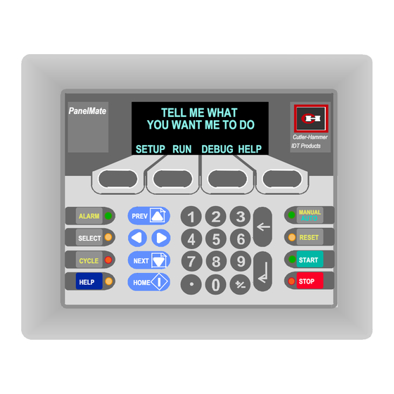
- Page 13 Configuring the System The page types are created and linked to each other using Windows-based software on a personal computer. The following steps A, B, C, D, E and F represent stages in the process of configuring a typical PanelMate 500 operator interface application. TELL ME WHAT PanelMate YOU WANT ME TO DO...
- Page 14 Additionally, the software provides Windows-based editors for System Parameters, PLC Name and Port Table, System Online Labels and Message Library: System Parameters Set up system wide options such as Passwords, Audio Levels, Scan Delays, and Remote Acknowledgment of Alarms PLC Name & Port Table Set up PLC communications and configure the PanelMate 500 ports System Online Labels Customize labels built into the system.
- Page 15 Notes to Previous Users of PanelMate 1. Although PanelMate 500 shares similar screen-based "objects", mathematical capabilities and PLC communication software as other PanelMate family members, the small display size changes the way an operator interacts with the unit. With other PanelMate units, operators actively select from a small library of detailed pages (typically 10 or 20), to “navigate”...
- Page 16 2. The keypad layout is new. There are four Soft Function Keys located below the display area. These keys are similar to the control buttons located to the right of the PanelMate display and have different definitions on different pages. They are used to write data to a PLC or to change pages.
- Page 17 7. The Setup Page provides the functionality found on the Setup Page of PanelMate. It permits contrast adjustment, access to system information, and can be used to select offline mode. 8. Note that all pages can be password protected. A check is made before page entry. The seven levels of passwords each have independent time-outs.
- Page 18 Chapter 2 How PanelMate Series 500 Units Work Online With PLCs In this chapter, you will learn: • What role a PanelMate Series 500 unit plays in factory automation • How PanelMate Series 500 partners with a PLC • How operators interact with PanelMate Series 500 •...
- Page 19 What Role a PanelMate Series 500 Unit Plays in Factory Automation Conventional operator stations consist of individual devices (pushbuttons, lamps, etc.) hard-wired to I/O points on a PLC. How PanelMate Series 500 Units Work Online With PLCs...
- Page 20 The PanelMate Series 500 is an electronic operator station which replaces conventional operator stations and associated hard-wired devices: TELL ME WHAT PanelMate YOU WANT ME TO DO Cutler-Hammer SETUP RUN DEBUG HELP IDT Products MANUAL ALARM PREV AUTO RESET SELECT START CYCLE NEXT...
- Page 21 Conventional hard-wired operator stations connect to PLCs symbolically as shown in this diagram: PLC Processor I/O Communication Control Operator Interface I/O Logic Control I/O Operator Interface Logic 456.32 PUSH Plant Devices Operator HI ALARM Interface On the operator station shown above: •...
- Page 22 PanelMate Series 500 connects to PLCs symbolically as shown in this diagram: PLC Processor I/O Communication Control Logic Control I/O Memory Savings Control Buttons Numeric Entry Operator Plant Devices PanelMate Series 500 Interface Logic a) direct serial or network connection OR b) I/O network connection PanelMate Series 500 performs all the same control and monitoring functions as the devices on a hard-wired operator station, plus adds many more capabilities.
- Page 23 How PanelMate Series 500 Partners with a PLC PanelMate Series 500 units can • communicate to nearly 100 varieties of PLC models • communicate directly to one PLC or to multiple PLCs on a PLC network • communicate to as many as 10 networked PLCs simultaneously from the same “page” (screen) PanelMate Series 500 online units physically connect to PLCs or their networks via cabling directly to a PLC port, network connection node or interface module (depending on the...
- Page 24 PanelMate Series 500 online units feature extensive built-in capabilities to perform mathematical calculations, alarm annunciation, and more. And, they can store data in their own internal memory locations called “scratchpad” addresses. This means that: • PanelMate Series 500 eliminates the extensive additional PLC ladder logic which might otherwise be needed to support operator interface activities When PanelMate Series 500 is connected to a remote I/O network such as Allen-Bradley’s, it communicates differently than with all other serial or network connections.
- Page 25 How Operators Interact With PanelMate Series 500 Operators interact with PanelMate Series 500 in two basic modes: • they monitor events through PanelMate Series 500 • they take action through PanelMate Series 500 Monitoring is supported with the following PanelMate Series 500 capabilities: •...
- Page 26 Taking action is supported by permitting operators to press the equivalent of momentary- contact control buttons and to perform numeric entry. • online units feature 8 control buttons whose functions are configurable - a separate keypad exists for numeric entry PanelMate TELL ME WHAT YOU WANT ME TO DO...
- Page 27 Standardized On-screen Tools Called “Objects” The most basic job of a PanelMate Series 500 online unit is to replace the functions of traditional hard-wired operator station devices such as pushbuttons, lamps and message displays. To replace each category of hard-wired device, PanelMate Series 500 supplies a specific visual tool or “object”...
- Page 28 PanelMate Series 500 Alarm Annunciation Capability PanelMate 500 lets users define alarms for the system within a separate Alarm Properties Editor. When an alarm situation is detected, PanelMate Series 500 responds by: • generating a separate message and blinking the “alarm” LED for the dedicated Alarm Function Key •...
- Page 29 Additional Features Available PanelMate Series 500 has many additional features available to provide convenience and flexibility in partnering with PLCs. These features are accessible from the “System Parameters” section of the configuration software. A few of the often-used capabilities include: •...
- Page 30 A Simulation Built Into Each Online Unit Every PanelMate 500 online unit includes an extremely informative simulation which is installed at the factory during the manufacturing process. We strongly recommend that even before you continue with installing software and other startup tasks, you apply power to a PanelMate 500 online unit and review the simulation.
- Page 31 2-14 How PanelMate Series 500 Units Work Online With PLCs...
- Page 32 Chapter 3 From Opening the Boxes to Running Online: A Master Startup Flowchart In this chapter, you will learn: • The overall sequence of steps necessary to configure, load and run a PanelMate Series 500 unit • The chapters in this manual providing specific startup guidance •...
- Page 33 The Master Startup Flowchart Start by Assembling: PanelMate Configuration software VGA Personal Computer Ladder Diagram(s) for partner PLCs ê See Chapter 4 Load the Software To Your Personal Computer ê See Chapter 5 Start a New Configuration (set of pages) ê...
- Page 34 Development Checklist 1. Draw a flow chart of the application. 2. Determine the interaction between the pages and the function key/ LED pairs. 3. Begin to define page operation. Begin to assign page names and numbers and linkages. Use the Previous and Next navigation keys to maximum advantage. Review security password usage on a per page basis.
- Page 35 A Master Startup Flowchart...
- Page 36 Chapter 4 Installing the Configuration Software In this chapter, you will learn: • System requirements • Using the Setup Program to install the software Installing the Configuration Software...
- Page 37 System Requirements The following table shows the software and hardware requirements for installing and running the PanelMate 500 Configuration Software. Operating System MS-DOS version 5.0 or later plus any of the following: Microsoft Windows version 3.1 or later Windows for Workgroups version 3.1 or later Windows 95 Microprocessor 386 required (486/66MHz or higher recommended)
- Page 38 Running the Setup Program to Install the Software The following procedure describes how to install the PanelMate 500 Configuration Software to your computer’s hard disk from floppy disks. To install PanelMate 500 Configuration Software on your computer: 1. If you are using a virus-detection utility, disable it before running Setup. If you do not disable the utility, Setup may conflict with it and not run.
- Page 39 Installing the Configuration Software...
- Page 40 Chapter 5 Creating a New Configuration In this chapter, you will learn: • About the PanelMate 500 Configuration Editor Main Screen • How to start a new Configuration Creating a New Configuration...
- Page 41 Before Getting Into the Software If you have been following the Getting Started User’s Guide in sequence, you have now loaded your configuration software onto your PC and are ready to try creating a sample configuration. The remainder of this chapter 5, plus chapters 6 through 11 will show you how to start with a “blank screen”...
- Page 42 The PanelMate Configuration Editor Main Screen The Setup program creates a group within your Windows Program Manager named “PM500” , featuring the PanelMate 500 Configuration Software icon. Double click on the icon to launch the program, bringing you to the Main Screen. From this point forward in the Getting Started manual, perform the numbered steps whenever they appear in the Œ...
- Page 43 Starting a New Configuration Select the “New” button on The Page Editor section of the Main Screen to indicate that you wish to create a new configuration (set of displays for an online unit). This will bring up the New Configuration dialog box used to specify basic information about your new configuration.
- Page 44 Chapter 6 Assigning PLC Communications In this chapter, you will learn: • Where to find the necessary communications setup information. • How to configure the PLC Name and Port Table. Assigning PLC Communications...
- Page 45 Determining Communication Information This chapter explains how to setup communications to a PLC. Additional PLCs can be added after successfully establishing communications to a single PLC. The following communications information needs to be determined from the appropriate PLC Driver Manual in order to complete this section. Communications Parameters: •...
- Page 46 Configuring the PLC Name and Port Table Start from an open PanelMate Configuration: Œ Double-click on Properties • Double-click on PLC Name and Port Table Assigning PLC Communications...
- Page 47 Configure Port Parameters Information: Setup the Port Parameters as follows: Œ Leave selection Ž Click on and edit on port 1 the Local ID address, if needed • Click on Device and select the proper driver Tips: • Port 2, I/O port, and “Printer Active on Port 2” are only visible on 4-line display versions of the product.
- Page 48 Continue configuring the PanelMate communication port as follows: Œ Select Port Settings • Select proper communication settings for the port Ž Select OK to close the Port Settings dialog box Assigning PLC Communications...
- Page 49 Configure PLC Name Parameter information: From the PLC Name and Port Table, select the “PLC Name” tab. Œ Click on Name field and edit name • Click on Model and select the proper PLC Model Ž Click on and edit the Remote ID address •...
- Page 50 Configuring the PLC Processor The PLC Processor or Communication module must be setupto match the values entered in the PanelMate Configuration Software. Reference the PLC Driver manual for specific PLC setup instructions. The following parameters are normally configured in the PLC using programming software or dip switches: •...
- Page 51 Assigning PLC Communications...
-
Page 52: Table Of Contents
Chapter 7 Creating New Pages In this chapter, you will learn: • Using the Main and Configuration Window Frames • A review of the five onscreen page types, plus the System page, Alarms and page linking • How to Create and Open a new page •... - Page 53 Using the Main and Configuration Window Frames Configurations are created and opened from the Main Window Frame. Components of a configuration are accessed from the Configuration Window Frame. Each configuration is contained within its own Configuration Window Frame. Components making up a configuration are automatically listed under the associated configuration name using a “tree view”.
- Page 54 A Review of the Page Types As was presented in Chapter 1, five types of onscreen pages may be configured within the PanelMate 500 configuration software. In addition, users may configure the 8 membrane keys and built-in LEDs as part of the “system page” configuration, and may also configure alarms for the system.
- Page 55 About the System Page and Alarms In addition to the 5 onscreen pages, the PanelMate 500 editor permits configuring certain “system” features which are always active, regardless which of the onscreen pages may be visible. The 8 membrane key control buttons and 8 (or 4) built-in LEDs may be configured using a System Page editor.
- Page 56 Creating New Pages (screens) Overview Flowchart Œ Create a new, blank page ê • Select page type ê Ž Complete page spreadsheets for PLC as as Repeat steps 1 through 4 necessary references, text, etc. as appropriate for each page type ê...
- Page 57 Creating a Page Add a page to a configuration as follows: Ž Select OK • Select Page Number, Name, Type, and Size Œ Select New Tips: • A new page may also be created by selecting “Page” then “New” from the menu bar.
- Page 58 Opening an Existing Page Open one or more existing configuration pages as follows: Double-click on Page to Open Tips: • Pages can also be opened by highlighting the page in the Configuration Window Frame and selecting “Open” • Use the Minimize button to minimize the page to an icon when editing multiple pages at once Creating New Pages...
-
Page 59: How To Configure A Data Page
How to Configure a Data Page The Data Page has a built-in editing feature which permits different types of data to be displayed on the Data Page. The Data Page supports the following types of data: Text, Conditional Indicator, State Indicator, Numeric Data, Alpha Display, and Bar Graph. To add a Data Page to a configuration, follow the steps for Creating a New Page and select Data for the Type under Page Properties. - Page 60 As shown in the following illustration, after selecting a bar graph object from the tool pallette, the bar appears at the top left of the display. When the cursor is double-clicked on the bar, the bar graph properties spreadsheet will appear. In this same fashion, any of the other 5 object types may be added to a data page.
- Page 61 The four soft function keys located just below the screen are configurable to be active when a Data Page is displayed. Each soft function key can be configured for any one of five actions: No Action, Momentary (set a bit to 1 then 0), Goto Page, Data Write (write a value to a reference), and User Defined (series of responses).
-
Page 62: How To Configure A Menu Page
How to Configure a Menu Page The Menu Page allows you to configure a numbered list of selections (i.e., menu). To add a Menu Page to a configuration, follow the steps for Creating a New Page and select Menu for the Type under Page Properties. To configure the Menu Page, click on Edit... -
Page 63: How To Configure A Change Password Page
How to Configure a Change Password Page The Change Password Page is used to allow operators to change passwords in Run Mode. To add a Change Password Page to a configuration, follow the steps for Creating a New Page and select Change Password for the Type under Page Properties. 7-12 Creating New Pages... -
Page 64: How To Configure A Setup Page
How to Configure a Setup Page The Setup Page allows you to set the Operator Station’s capabilities: adjusting the system’s contrast, getting system information, and entering Offline Mode. To add an Setup Page to a configuration, follow the steps for Creating a New Page and select Setup for the Type under Page Properties. -
Page 65: How To Configure A Maintenance Page
How to Configure a Maintenance Page The Maintenance Page allows you to access any resource (register, timer, etc.) used for setup and troubleshooting in the PLC. To add a Maintenance Page to a configuration, follow the steps for Creating a New Page and select Maintenance for the Type under Page Properties. -
Page 66: How To Configure The System Page
How to Configure the System Page The System Page refers to the set of 8 membrane keys plus built-in LEDs which are at the lower left and right of the front of every PanelMate 500 online unit. The keys and LEDs are assigned functions which are active “system-wide”... - Page 67 Double-clicking on the function key will bring up the Function Key Editor. When you have finished editing, click on OK to return to the System Page Editor. Tips: • For additional information about the Function Key Editor, select Help within the Function Key Editor spreadsheet.
- Page 68 From the System Page Editor, double-click on any LED to bring up the LED Properties Editor. Tips: • For additional information about the LED Editor, select Help within the LED Editor spreadsheet. Creating New Pages 7-17...
- Page 69 How to Configure Alarms Alarms are configured for any events on any page in the system using the Alarms editor. From the Properties listing for your configuration, double-click on Alarms to enter the Alarms editor. Click on Alarms 7-18 Creating New Pages...
- Page 70 This will display the Alarm Properties Editor, which can be used to specify alarm conditions. Tips: • For additional information about the Alarm Properties Editor, select Help within the Alarm Properties Editor spreadsheet. Creating New Pages 7-19...
- Page 71 7-20 Creating New Pages...
- Page 72 Chapter 8 Configuring with the Virtual Mentor Guided Operator Capability In this chapter, you will learn: • Explanation of the Virtual Mentor Option • Editing a Response Template • Response Template Example Configuring with the Virtual Mentor Guided Operator Capability...
- Page 73 Explanation of the Virtual Mentor Capability The Virtual Mentor™ Guided Operator Capability is available with online models 542VM and 542LM, to permit the operator station to perform “autopilot-like” functions. Without Virtual Mentor, the operator must monitor the status of the machine and make all decisions relating to its operation.
- Page 74 Virtual Mentor: * adds extensive built-in decisionmaking tools * can simplify the operator’s choices * can guide operators through sequences * can vastly simplify diagnostics * can perform actions without operator or PLC initiation * further reduces PLC programming These features can greatly ease tasks and decisionmaking for the operator. Virtual Mentor can be used to create very focused, “context-sensitive”...
- Page 75 To allow the Virtual Mentor Option feature in your configuration, in the Configuration Properties, select the box under Product Options labeled "Virtual Mentor - Guided Operator Capability". Note for this feature to be available in Run Mode, the Virtual Mentor Option must be available on the PanelMate 500 unit (either model 542LM or 542VM).
- Page 76 Editing a Response Template The Virtual Mentor Option permits the creation of "Response Templates" which are comprised of one or more "Condition/Response" pairs. In general, various system responses can be triggered based on defined conditions. Both the Data and Menu Pages provide access to the Response Template Editor. Click to call up Response Template Editor Configuring with the Virtual Mentor Guided Operator Capability...
- Page 77 The Response Template Editor contains a set of two tabbed dialog boxes used to determine Entry and Scanned actions. The Operator Station will evaluate each Entry condition once sequentially and execute the designated response(s) prior to displaying the current page. After the page is displayed, the Operator Station will evaluate each Scan condition and execute the designated response(s).
- Page 78 In the Condition field, enter the conditional expressions to be evaluated. You can select a condition in the Select Text field or you can enter a condition by typing in the field. In the Condition field, you can enter PLC references, ScratchPad references or Conditional Operators.
- Page 79 Response Template Example In this example, condition 1 will evaluate to be true every time page 18, Beverage Selection, is displayed. Therefore, ScratchPad register 1 will always be set to 0 (Off). (This resets the Beverage Selection on page entry.) After condition 1 has been evaluated, condition 2 will be evaluated.
- Page 80 Chapter 9 Saving the Configuration In this chapter, you will learn how to: • Save a configuration Saving the Configuration...
- Page 81 Saving Changes If changes were made to the application, the user is prompted to save the changes before the application is closed. Œ Choose File then Save As... • Choose a file name Select OK to save file Select Cancel to discard changes Tips: •...
- Page 82 Chapter 10 Compiling the Application In this chapter, you will learn how to: • Compile an application for downloading Compiling the Application 10-1...
- Page 83 Compiling an Application for Downloading Prior to downloading to the online unit, the application must first be compiled into a file as follows: Œ Choose File then Compile or click Compile icon Ž Select OK • Choose a filename for the application Tips: •...
- Page 84 Chapter 11 Transferring the Configuration to a PanelMate Series 500 Online Unit In this chapter, you will learn: • How to setup your Personal Computer and PanelMate Series 500 online unit • How to perform the file transfer process Transferring Configurations to a PanelMate 11-1...
- Page 85 PanelMate Transfer Overview This chapter explains how to transfer a configuration from a PC to a PanelMate Series 500 online unit. PanelMate requires two separate file types to operate. These files must be the proper version and loaded in the proper sequence for PanelMate to function properly. The two file types are: •...
- Page 86 Starting the PanelMate Transfer Screen When you have completed a configuration and have saved and compiled it, begin the transfer process by selecting PanelMate Transfer: Œ Select File • Select PanelMate Transfer Transferring Configurations to a PanelMate 11-3...
- Page 87 Setting up the Computer Communication Parameters The computer must be setup properly before the transfer process can begin: Œ Click on Port Parameters • Click on and select the computer Port and the transfer Baud Rate Tips: • Make sure that that the computer communication port that you select in the PanelMate Software is also set in your computer setup screen as a communication port and not a mouse port •...
- Page 88 Determining PanelMate System Information The System Information option reads and displays the version of PLC driver and configuration that is currently in the PanelMate. The first transfer is normally a reading of the parameters in PanelMate so that proper communications can be verified. Œ...
- Page 89 Selecting the PLC Drivers to Transfer The next step is to transfer the PLC driver that you have used in your configuration. Œ Click on Drivers • Click on and select the proper driver Ž Click on Add to Operation List Tip: •...
- Page 90 Selecting Options to Transfer Any special options that you have used in your configuration must next be transferred into the online unit. Options are “One Time Use” disks that enable each PanelMate to accept configurations that are using the following features: •...
- Page 91 Selecting the Configuration to Transfer After all other required items have been transferred, the configuration can be transferred to the online unit. Œ Click on Configuration • Click on, and select your configuration Tips: • The configuration to be transferred to an online unit must have a filename extension of .ovb, .ova, .olb or .ola.
- Page 92 Preparing the PanelMate for a Transfer The PanelMate must be changed from the normal online run mode into an offline transfer mode before downloading new files. The following steps must be performed to place the PanelMate into transfer mode: • Cycle power to the PanelMate unit •...
- Page 93 Starting the Transfer Process Begin the transfer process by clicking on “START.” The process will consist of: • Checking communications and displaying System Parameters of the PanelMate. • Transfer the PLC Driver • Transfer the Configuration Press Start • When complete, press Soft Function Key 4 (SFK4) to Exit and then Soft Function Key 1 (SFK1) to Run.
- Page 94 Chapter 12 Running the PanelMate Series 500 Unit Online With the PLC In this chapter, you will learn how to: • Start up a PanelMate Series 500 unit online with a PLC after completing all necessary file transfers Running Online With the PLC 12-1...
- Page 95 Running the PanelMate Series 500 Unit Online With the PLC After the download process is complete the PanelMate needs to be placed in the on-line mode: • Connect your PLC and verify the processor is in the Run Mode. • Cycle power to the PanelMate unit.
- Page 96 Appendix In this chapter, information is provided to: • Access and understand a set of communication startup configurations for many commonly-used PLCs - these startup configurations permit you to confirm PLC communications with your PanelMate 500 unit as part of your startup process •...
- Page 97 Communication Startup Configurations The part of the electronic operator station startup process which seems to produce the most common “stumbling blocks” is when a user first attempts to run the operator station online with a PLC. In the case of PanelMate 500, even if the configuration created by the user contains no syntax errors (it passes the “verify”...
- Page 98 Each startup configuration attempts to read a valid address which has been chosen for the particular PLC model. If the address is successfully read, the words “Communication Link Established” will appear on the screen of the PanelMate 500 online unit. Note that the first two lines of the page confirm the PLC to which communication has been established.
- Page 99 PLC Models Covered, and How to Proceed The following are the PLC models and types of communication for which communication startup files are supplied: Allen-Bradley PLCs SLC 500 family via DH 485 communication SLC 5/03 & 5/04 via A-B RS 232 serial communication (DF1 protocol) SLC 5/04 via A-B Data Highway Plus * Micrologix PLC via A-B RS 232 serial communication (DF1 protocol) PLC 5 family via A-B RS 232 serial communication (DF1 protocol)
- Page 100 If you plan to use one of the PLC models and communication approaches noted previously, we recommend that you complete these steps: 1. Examine the charts which follow, to determine the settings you will need to assign (baud rates, PLC ID numbers, etc.) in the PLC model you are using. Whenever possible, the settings are the default settings for the PLC model.
- Page 101 The Communication Startup Reference Charts Configuration Name ABDH485 PLC Type Allen-Bradley SLC 500 family PLC driver to transfer to PM 500 Allen-Bradley DH 485 Communication type A-B DH 485 PanelMate Port assigned PanelMate ID assigned Electrical Connection 485-2 Baud Rate 19200 Data Bits Stop Bits...
- Page 102 Configuration Name ABSLCDHP Allen-Bradley SLC 5/04 PLC Type PLC driver to transfer to PM 500 Allen-Bradley DH/DH+ Communication type Allen-Bradley Data Highway Plus PanelMate Port assigned PanelMate ID assigned Electrical Connection Baud Rate Data Bits Stop Bits Parity PLC ID needed PLC address referenced S:1/7 PLC port used...
- Page 103 ABSER232 Configuration Name Allen-Bradley PLC 5 family PLC Type PLC driver to transfer to PM 500 Allen-Bradley Serial Communication type Allen-Bradley Serial (DF1 protocol) PanelMate Port assigned PanelMate ID assigned Electrical Connection RS 232 Baud Rate 19200 Data Bits Stop Bits Parity none PLC ID needed...
- Page 104 Configuration Name ABDHP Allen-Bradley PLC 5 family PLC Type PLC driver to transfer to PM 500 Allen-Bradley DH/DH+ Communication type Allen-Bradley Data Highway Plus PanelMate Port assigned PanelMate ID assigned Electrical Connection Baud Rate Data Bits Stop Bits Parity PLC ID needed PLC address referenced S:1/7 PLC port used...
- Page 105 CHD200 Configuration Name Cutler-Hammer D200 PLC Type PLC driver to transfer to PM 500 Cutler-Hammer D200/D500 Communication type serial RS 422 PanelMate Port assigned PanelMate ID assigned Electrical Connection RS 422 Baud Rate 9600 Data Bits Stop Bits Parity none PLC ID needed PLC address referenced R62F...
- Page 106 Configuration Name GECMM422 General Electric Series 90 PLC Type PLC driver to transfer to PM 500 GE Series 90 point-to-point Communication type GE Series 90 point-to-point PanelMate Port assigned PanelMate ID assigned Electrical Connection RS 422 Baud Rate 19200 Data Bits Stop Bits Parity PLC ID needed...
- Page 107 A PanelMate 500 Product Demonstration A PanelMate 500 product demonstration is described below using the built-in “coffee machine” example Introduction The PanelMate 500 unit is available in 6 online models. Four of these models are: a 4-line vacuum fluorescent display (VFD) unit, a 4-line liquid crystal display (LCD) unit and 2-line versions of each display type.
- Page 108 Demonstration To illustrate a few of PanelMate 500’s capabilities using our “coffee machine” example, just follow these steps with your PanelMate 500: After initial power-up, the PanelMate 500 will display a Welcome page, including the invitation to press the first soft function key beneath the page for “Run”, or the fourth soft function key for “Readme”.
- Page 109 The choices from the Select Beverage page are: 1 Coffee 2 De-caffeinated 3 Tea Press 1 to select Coffee and link to the Confirm Selection page. On the Confirm Selection page, press the Continue soft function key just below the display area.
- Page 110 The first time you complete the previous cycle, you will link to the “Brewing Complete” page. If you then press the Continue soft function key, you can start the cycle over again. When you complete the second coffee brew cycle, the system will link to the Out of Beverage page, and will generate an alarm.
- Page 111 Comments About the Online Simulation After you have performed the previous demonstration, you may wish to return to the Main Menu and explore other selections in addition to the ones already noted. The most important concept illustrated by the “coffee machine” is that the PanelMate 500 can alter the way in which it leads operators through a sequence, depending upon conditions at the time.
- Page 112 By clicking on File, then selecting Print Report, you can print your choice of Configuration Properties or individual Pages for the coffee machine simulation. If you print everything available, you will generate nearly 50 pages of information. Instead, we recommend you select and print only a limited selection of pages.
- Page 113 * Shows a Menu Page appearance. Page #18 * Shows that the three selections available to operators (1, (prints 1 sheet) 2 or 3) set the scratchpad variable “fbeverage” equal to 1, 2 or 3 and then assign the screen to Go To page 19. * Shows that a Response Template (Virtual Mentor feature) checks several scratchpad variables (e.g.
- Page 114 Shows a Data Page appearance. Page #8030 Shows static text content and position on display. (prints 1 sheet) Shows position of Numeric Data Object, plus all of its parameters and references. Shows Bar Graph Object, plus all of its parameters and references.
- Page 115 A Configuration Containing All Page Types and All Object Types Introduction In addition to the coffee machine simulation already described in this Appendix, there is another simulation available on the EXAMPLES diskette. It is a configuration called ASAMPLE1, and it contains 27 pages designed to provide examples of every one of the 5 onscreen page types, all 6 object types, and the system page.
- Page 116 Before you begin the process, be aware that the ASAMPLE1 file is preconfigured to use the Cutler-Hammer D50/300 PLC driver, even though the simulation runs in the online unit without any connection to a PLC. If you did not load the Cutler-Hammer D50/300 PLC driver to your PC when you installed your PanelMate 500 configuration software, please return to Chapter 4 of this Guide to install it at this time.
- Page 117 The previous process should result in presentation of the directory for the 27 pages which comprise the ASAMPLE1 application. If you do not have the Cutler-Hammer PLC driver available with your software, you will want to select another PLC type, corresponding to a driver which IS installed in your PC.
- Page 118 2. Click on the PLC Name tab. Double-click on the Model field, click on a model to select it, then click on the adjacent Remote ID field. This process should assign a default set of entries to all 3 field types. 3.
- Page 119 Demonstration The ASAMPLE1 configuration illustrates all 5 onscreen page types, all 6 data object types, plus the offscreen “system page” (the use of the 8 control buttons, built-in LEDs and numeric entry pad). After initial power-up, the PanelMate 500 will display a Startup page, including the invitation to press the fourth soft function key for “Reset”.
- Page 120 Once the online unit indicates that it is Ready: Press the blue “Next” key to advance to page 2, which is the HOME page. Press the first soft function key, labeled “Next” to advance to page 100, which is a Data Page.
- Page 121 The suggested actions which follow will take you through a “tour” of multiple page types. The first segment of the tour explores the object types available on Data Pages (probably the most commonly used page type). From page 100, press the first soft function key to link to Data Page 3. Press the blue Next key repeatedly, to examine Data Pages 4 through 8.
- Page 122 Exploring the ASAMPLE1 Configuration If you have run the ASAMPLE1 simulation, you now may wish to look more closely at the configuration. Begin by opening the ASAMPLE1 configuration with your PanelMate 500 configuration software, as was described earlier in this Appendix. By clicking on File, then selecting Print Report, you can print your choice of Configuration Properties or individual Pages for the ASAMPLE1 simulation.
- Page 123 Note that the ASAMPLE1 application was constructed WITHOUT using the Virtual Mentor Response Template feature. The following are details in the printouts that you should look for: Selection Illustrates Page Linkage * Shows appearance of all onscreen pages in the Summary application.
- Page 124 Page #8 * Shows a Data Page appearance. (prints 2 sheets) * Shows static text content and position on display. * Shows definition of soft function keys 2, and 4, which are used to increment and decrement an internal scratchpad variable. * Shows position of Numeric Data Object, plus all of its parameters and references.
- Page 125 Twelve Helpful Reminders 1. The PanelMate 500 Operator Station design is based on the concept of linking pages to each other. Page changes are possible with screen defined soft function keys, menu selection, logic selection, PLC page change selection, or the use of the navigation keys.
- Page 126 8. There are internal registers known as ScratchPads that have the syntax [SP,xxx] where xxx is any printable ASCII character (letter or number). You cannot use a space character. Keep names short as they consume memory! ScratchPads are stored internally as signed 32 bit values. (They are integers and therefore cannot contain implicit decimal points.) 9.
- Page 127 A-32 Appendix...
Need help?
Do you have a question about the Cutler-Hammer PanelMate 500 Series and is the answer not in the manual?
Questions and answers