Table of Contents
Advertisement
Quick Links
Advertisement
Table of Contents

Related Manuals for SPI C170 CHLORINE


Summary of Contents for SPI C170 CHLORINE
- Page 1 User Manual SPI-C170 CHLORINE...
-
Page 3: Table Of Contents
SPI – C 170 CHLORINE Index SPI-C170 ............................. 1 1. INTRODUCTION ........................3 2. DESCRIPTION AND OPERATION ....................5 3. SAFETY ............................. 7 4. TRANSPORT AND STORAGE ....................... 8 5. ASSEMBLY AND INSTALLATION ....................9 6. COMMISSIONING ........................11 7. OPERATION ..........................12 8. -
Page 4: Spi-C170
The manual for the SPI-C170 is meant for the following authorized employees: Electrotechnical staff Watertechnical staff Laboratory staff This manual is made for the installation and operation of the SPI-C170 Chlorine. In this manual you will find various enumeration characters: Enumeration of functions (1.) -
Page 5: Introduction
SPI – C 170 CHLORINE 1. Introduction Purpose of the SPI-C170 The SPI-C170 is designed for correctly measuring, controlling, and guarding a water treatment process. The SPI-C170 is suitable for the following sectors: Water companies Other locations that measure and regulate Chlorine levels... - Page 6 No higher supply voltage than 12VDC is used. Background information After years of collaboration with a team of specialists in the field of water treatment, the SPI measure and control system was introduced. The SPI-C170 is the fourth generation of its kind. The SPI-C170 is a water control system based on the colorimetric measuring method that utilizes reagents colour discoloration.
-
Page 7: Description And Operation
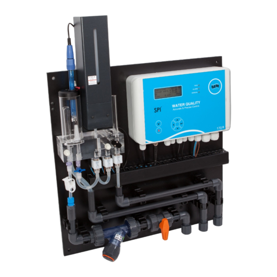
When you have the optional SPI-REMOTE software, it is possible control and see the information of the SPI using the network or internet. With the optional SPI-GRAPHS software, you can use the data downloaded with the remote software, and use this for data acquisition. - Page 8 SPI – C 170 CHLORINE Analysis-unit Control-unit Figure 2.1.1. Buffer jar Reagent vial Filling tube Drain tap Supply valve Reagent valve Overflow tube Drain valve Filter Figure. 2.2.1 V1 20130904...
-
Page 9: Safety
3. Safety Safety regulations The SPI-C170 is as careful as possible designed with the eye on safety. We tried to reduce the safety risks to a minimum. The SPI-unit is supplied with a 12VDC adapter via a power outlet. -
Page 10: Transport And Storage
11. Take the SPI-unit off the wall. Transport 1. After disassembly, make sure the SPI-unit is placed in a firm box, with the components facing upwards. This may also be standing upward. 2. Protect the corners well from impacts. -
Page 11: Assembly And Installation
The power outlet is in an acceptable range of the SPI-unit (100-240VAC 47-63Hz) The return to the buffer tank is taken care of and brought to where the SPI is going to be The drain to the sewer is taken care of and brought to where the SPI is going to be Please follow the instructions for installing the SPI-C170: 1. - Page 12 SPI – C 170 CHLORINE Reagent vial Analysis-unit Buffer jar Control-unit Supply and drain Figure 5.1.1. Figure 5.2.1. V1 20130904...
-
Page 13: Commissioning
15.4. Indication LEDs After the SPI-C170 has configured itself, the blue LED will start flashing. On the front panel of the SPI-C170 control-unit are a total of 3 LEDs. The explanation of these LEDs are as following: Blue ON/OFF ;... -
Page 14: Operation
SPI – C 170 CHLORINE 7. Operation Navigation Using the keyboard, you can perform all operations. You simply follow the options through the menu structure on the display. Navigating through the menu structure is done using the arrow buttons. The display displays a maximum of 4 lines a time. - Page 15 SPI – C 170 CHLORINE Selecting a choice When you made a decision in the menu, you can select and enter this option by navigating the cursor to the correct line using the arrows. This cursor is always at the end of the sentence, and will flash.
-
Page 16: Main Menu
Using the main menu, all important functions of the SPI-C170 can be reached. The main menu is what you get to see after starting the SPI-C170, and is where you always get back to. The main menu consists of the following options: ... - Page 17 SPI – C 170 CHLORINE 9. Overview You can find the most important measurements and values and relevant information in the overview menu as in figure 9.1. You can enter this menu by selecting Overview from the main menu. A special character is present behind some of the lines indicating its status. More about these characters can be read in chapter 12.1.
- Page 18 SPI – C 170 CHLORINE 10.Calibration All measurements connected to the SPI-C170 must be regularly checked and, if necessary, be calibrated. This ensures the quality of the measurements made. You can enter this menu by selecting Calibration from the main menu.
- Page 19 SPI – C 170 CHLORINE 10.1.1 Calibrating with handmeter When you select Calibrating with handmeter the menu as in figure 10.1.1.1 will appear. Here you can perform a calibration using a third party handmeter. Now perform the following instructions: Take a sample from the drain tap under the buffer jar and measure this with the handmeter.
- Page 20 SPI – C 170 CHLORINE 10.1.2 Calibrating with fluids Calibrating using fluids guarantees a more dependable calibration then when using a handmeter. The system lets you first perform a zero point measurement, and after that a measurement using a control fluid of your choice. The measurement will then be calibrated at 2 points.
- Page 21 SPI – C 170 CHLORINE If the value is correct, select and press enter ( ) on Begin 0.52 mg/l cal. The menu of figure 10.1.2.3 now appears. Cal at 0.52 mg/ l Val ue 0.51 mg/ l Exp ected: 0.52 mg/ l...
- Page 22 SPI – C 170 CHLORINE 10.1.3 Reset Calibration If you are not satisfied with the current Chlorine calibration or you don’t have the right tools to calibrate, you can reset the calibration settings to the factory settings. To do a calibration reset, select Restore calibration from the Chlorine calibration menu.
- Page 23 2. Take a new vial and place it in the designated holder on top of the analysis-unit. 3. Replace the standard cap of the vial and replace this with the cap supplied with the SPI-C170. This cap contains 2 holes; one for the tube, the other for aeration.
- Page 24 SPI – C 170 CHLORINE 5. By now the menu as in figure 10.1.4.2.2 has appeared. The cell is prepared. 6. You are asked to place your finger on the top of the filling tube. Do this and ensure an airtight seal.
- Page 25 Cycle time (The time the SPI-C170 will ‘wait’ between 2 measurements in seconds. Setting this at 300, means that the SPI will wait 5 minutes, before the next measurement starts. If the colour valve time is set at 0, the automatic reagents colour dosing is activated. This means that the dosing of a shot of reagent colour will be adapted to the use of the reagent.
- Page 26 More time means fewer measurements, but it saves more reagents colour. The SPI-C170 will temporary stop measuring and controlling as long as this menu is opened. The pumps will remain pumping at the same level as before this menu was opened.
- Page 27 SPI – C 170 CHLORINE 10.2 When you select pH from the calibration menu, the menu as in figure 10.2.1 will appear. In this menu it is possible to calibrate the pH. For calibrating the pH value, it is important to have the right tools at hand. The pH is calibrated using 2 independent constant buffer solutions with different pH values.
- Page 28 SPI – C 170 CHLORINE 4. Gently stir the electrode through the solution for about a minute. 5. Check the value at Actual pH. Wait for this value to get stable, then confirm with ( 6. Now flush the electrode with clean water.
- Page 29 SPI – C 170 CHLORINE 11 Settings In the settings menu it is possible to change the settings of specific parts of the SPI-C170. You can enter this menu by selecting Settings from the main menu. You can choose between the following submenus: ...
- Page 30 SPI – C 170 CHLORINE 11.1 Chlorine settings When you chose for Chlorine settings in the previous menu, you’ll see the screen as in figure 11.1.1. Here you can view or change the following settings: Hi alarm day (when the Chlorine measurement exceeds this value in the dayhours, an alarm will be given) ...
- Page 31 Alarm del day (The delay in seconds after an alarm will be given. A too short time may cause false alarms when there is a bad measuring present) Delta (this setting controls the maximum and minimum pump setting. The SPI-C170 calculates the average pump control. The pump cannot go over xx% of this average value) ...
- Page 32 The pump cannot go over xx% of this average value) Prop factor (his setting controls the proportional gain of the pH controller system. The SPI- C170 constantly calculates the difference between the setpoint and the actual pH value. The more difference, the faster or slower the pump will work.
- Page 33 SPI – C 170 CHLORINE Pump max % (the maximum percentage at which the pump will work) Max pulse time (the maximum time at which the pump can pump on maximum setting. If after this time the pump is fully pumping, and the measured value still has not reached the desired setpoint, there must be something wrong) Delta, prop factor, and int factor are advanced settings.
- Page 34 SPI – C 170 CHLORINE 11.2 Flow settings When you chose for Flow settings in the settings menu, you’ll see the screen as in figure 11.3.1. Here you can view or change the following settings: Alarm % (when the flow falls below this value, an alarm will be given) ...
- Page 35 Year (the years of the current date) It could happen that the SPI-C170 has reset the date & time settings at a power failure. If this is the case, the SPI will start counting from it’s default date and time values. The cause of this is most likely a bad battery.
- Page 36 SPI – C 170 CHLORINE 11.5 Day/night settings When you chose for Day/night settings in the settings menu, you’ll see the screen as in figure 11.5.1. Day start hour : Day start min Nig ht start hou r: 2 1 Nig ht start min : Figure 11.5.1.
- Page 37 If you don’t want to use this function, set the time at Time min to 0. The SPI will the function as normal. When you set a long time, keep in mind this will extend the total measuring cycle, it is only profitable when you have a long cycle time.
- Page 38 All current alarms and their alarm values will be shown in the Alarms menu. If an alarm has presented itself, the red LED will flashing on the keypad of the SPI-C170. You can enter this menu by selecting Alarms from the main menu.
- Page 39 In this case, the flow protection is turned off. More about this in chapter 13. Not present or maintenance mode (X) This character indicates the measurement is not present on the SPI and has been turned off. It can also mean the user is making maintenance on this part.
- Page 40 12.2 Alarm contact The SPI-C170 contains an alarm contact. This is a potential free contact that can be used to transmit the alarm signals to equipment of third parties. The alarm contact is closed when an alarm is being detected on the SPI.
- Page 41 SPI – C 170 CHLORINE 12.3 Solving alarms With correct use and regular maintenance, the least hardware errors will occur. For maintenance, see chapter 15. For solving problems you follow the following steps: 1. Check the problem, you can do this by selecting Alarms from the main menu. You are able to see the active alarm here.
- Page 42 SPI – C 170 CHLORINE Example On the keypad, the red LED is flashing. The alarm “A09: pH PUMP” is shown on the Alarm menu. This alarm means that the pump has been at full power for over a course of <1800> seconds (this time is adjustable), and the pH value is still high.
- Page 43 The temporarily turning off of the SPI-C170 with data preservation, is called the hot start As the unit is commissioned for a longer period of time, the battery ages. This is causing the SPI no longer retaining the clock settings. As soon as this seems to be the fact, we advise you to take steps to replace the battery.
- Page 44 SPI – C 170 CHLORINE 13.Manual operation The SPI-C170 contains the possibility to let the user control the Chlorine or the acid pumps on manual or semi-automatic mode. When you select Manual operation from the main menu, the screen as figure 13.1 appears.
- Page 45 SPI – C 170 CHLORINE Setting mode The set the right mode for a pump, you select the mode of that specific pump, and press enter ). You can fill in the following values for each mode: 1. Automatic 2.
-
Page 46: Reports
SPI – C 170 CHLORINE 14.Reports When you select Reports from the main menu the screen as figure 14.1 appears. In this menu you can read back and check various reports such as: 1. Alarm reports 2. Calibration reports 3. Maintenance services reports 4. - Page 47 SPI – C 170 CHLORINE When you select Calibration reports from the previous menu, the screen as in figure 14.2.1 appears. In this screen you can see all logged calibrations. The first log you see is the most recent. 201 1-06-03 14:4 5 C01 : Hand Cl Ca libr .
- Page 48 SPI – C 170 CHLORINE When you select Maintenance reports from the previous menu, the screen as in figure 14.3.1 appears. In this screen you can see all logged maintenance services. The first log you see is the most recent. The log screen consists of a date and time, followed by a system code and description.
-
Page 49: Maintenance
SPI won’t send out alarms 15.1 Regular maintenance For correct operating of the SPI-C170 it is important to regularly check on the correct operation of the unit, and keeping everything clean. This implies: Cleaning and keeping dry ... - Page 50 Every once in a while we advise to check the measurements for abnormalities, and when necessary, to calibrate them. When this is the case, calibrate the measurements of the SPI-C170 with well calibrated equipment of third parties. More about calibrating is described in chapter 10.
- Page 51 The valves are not supposed to dry with water, reagent, or other fluids containing chemical components. If you want to store the SPI-unit for a longer period, please follow the intructions as described in chapter 4.1. The valves may never be opened.
-
Page 52: Configuration
16. Configuration When you select Configuration from the main menu, the screen as figure 16.1 appears. With the help of this menu you can check and change various settings used for the configuration of your SPI system. The menu contains the following options: 1. - Page 53 Acid pump p/m (Fill in the maximum amount of pulses of your acid pump) Extern contact (Set if you want to be able to connect the SPI to the internet (1) or not (0)) Log period (Set the time in seconds the SPI system waits before creating a new log report) (to be continued on next page) Chl .
- Page 54 13. Cell alarm delay (Set the time in seconds the system delays the alarm of starting and complete pollution) 14. System ID (Set a custom identification number to this SPI for recognition. The numbers 1 – 254 can be used) 15.
- Page 55 When you chose for Version info in the Configuration menu, the screen as in figure 16.2.1 appears. In the version information menu it is possible to view the following information: 1. Software (the current version of the SPI-C170 Chlorine software) 2. System ID (Your custom system ID of this SPI model) You can use this information if the supplier asks for this for technical assistance.
- Page 56 Because of the discolouration, the water will get more dark, and absorb more light. When this happens, less light will fall on the receiver, resulting in less voltage. The SPI will measure this change. A measurement without reagents colour should give an internal value of around 1000. A good measurement with reagents colour added will be much lower.
- Page 57 SPI – C 170 CHLORINE 16.3.2 Calibrating zero value When the zero value starts to differ a lot from the normal value of 1000, it is important to check if the cell is clean. If the cell is clean, the cell might need to be calibrated. Calibrating implies that the zero value must be set back to its default value of 1000.
- Page 58 System reset The SPI-C170 contains an option to reset the system using the screen instead of taking out the adapter out of the socket. This way, you can reset the SPI using the SPI-REMOTE software. When you choose System reset in the configuration menu, you see the screen as figure 16.5.1. If you press ( in this menu, the SPI-C170 will be reset using the hot start method.
-
Page 59: Decommissioning
SPI – C 170 CHLORINE Decommissioning If you’d like to decommission the SPI-C170 for (longer) periods, follow the below procedure: 1. Remove the adapter from the power outlet. 2. Remove the reagents colour vial from the holder an rinse the tube with clean water. (please take the necessary safety precautions). -
Page 60: Discarding
SPI – C 170 CHLORINE 18. Discarding The SPI-C170 contains electronic components. Inform to the possibilities to seperate and recycle these components during discarding. Remove possible chemical remains like Chlorine or the corresponding reagents colour and discard these as chemical waste. - Page 61 SPI – C 170 CHLORINE Notes V1 20130904...
- Page 62 SPI – C 170 CHLORINE SPI Europa SPI Canada en Noord Amerika SEM Waterbehandeling B.V. Sanecotec www.semwaterbehandeling.nl www.sanecotec.com info@semwaterbehandeling.nl sales@sanecotec.com V1 20130904...
Need help?
Do you have a question about the C170 CHLORINE and is the answer not in the manual?
Questions and answers