
Subscribe to Our Youtube Channel
Related Manuals for Rheem RKKN-B073 Series


Summary of Contents for Rheem RKKN-B073 Series
- Page 1 INSTALLATION INSTRUCTIONS Package Gas Electric Featuring Industry Standard R-410A Refrigerant RKKN-B073 (6 TON) SERIES ACCREDITED ISO 9001:2008 92-23577-157-00 (BASED ON 92-23577-141-03)
-
Page 2: Table Of Contents
TABLE OF CONTENTS I. Table of Contents ....................2 II. Introduction ......................3 III. Checking Product Received ..................3 IV. Specifications......................3 A. General ......................3 B. Major Components....................3 C. R-410A Refrigerant ...................3 1. Specifications of R-410A................3 2. Quick Reference Guide for R-410A ..............4 3. Evaporator Coil/TXV ..................4 4. -
Page 3: Introduction
Recognize this symbol as an indi- cation of Important Safety II. INTRODUCTION This booklet contains the installation and operating instructions for your combination gas Information! heating/electric cooling unit. There are some precautions that should be taken to derive maximum satisfaction from it. Improper installation can result in unsatisfactory operation or dangerous conditions. -
Page 4: Quick Reference Guide For R-410A
lines, or be allowed to accumulate in storage tanks. Leak checking should never be done with a mixture of R-410A and air. Leak checking can be performed safely with nitrogen or a mixture of R-410A and nitrogen. 2. Quick Reference Guide For R-410A •... -
Page 5: Unit Dimensions
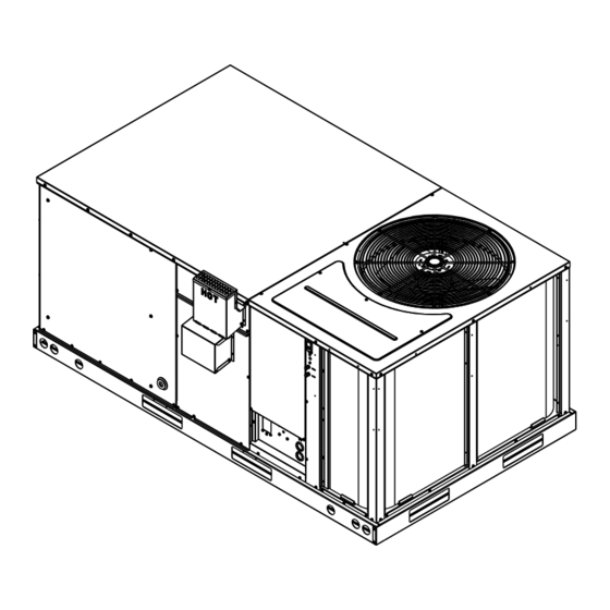
VI. UNIT DIMENSIONS RKKN 6 TON [21.1 kw] mOdELS FIGURE 1 OUTDOOR FAN OUTDOOR COIL ST-A1224-01 FIGURE 2 TOP VIEW 4-1/2 [660] [114] 4-5/8 2-3/8 [118] 2-5/32 [60] 4.502 [55] [114] RETURN 13-1/8 SUPPLY [333] [508] 43-7/32 [1098] 13-1/8 [333] 2-3/8 77-15/32 2-3/8... - Page 6 FIGURE 3 BACK vIEw ST-A1148 FIGURE 4 SIdE vIEw ST-A1224 FRONT vIEw FIGURE 5 ST-A1224...
-
Page 7: Installation
VII. INSTALLATION WARNING NEvER TEST FOR GAS LEAKS wITh AN OPEN FLAmE. USE A A. GENERAL Install this unit in accordance with The American National Standard Z223.1-latest edition COmmERCIALLy AvAILABLE booklet entitled “National Fuel Gas Code,” and the requirements or codes of the local SOAP SOLUTION mAdE SPECIFI- utility or other authority having jurisdiction. -
Page 8: Outside Installation
FIGURE 6 WARNING OUTSIdE SLAB INSTALLATION. CLOSET dISTRIBUTION SySTEm. SLAB FLOOR CONSTRUCTION. ThIS UNIT mAy BE USEd TO hEAT ThE BUILdING OR STRUCTURE dURING CONSTRUCTION IF ThE FOLLOwING INSTALLATION REqUIREmENTS ARE mET. INSTALLATION mUST COmPLy wITh ALL INSTALLATION INSTRUCTIONS INCLUdING: •... -
Page 9: Attaching Exhaust And Combustion Air Inlet Hoods
C. ATTACHING EXHAUST AND COMBUSTION AIR INLET HOODS ImPORTANT: do not operate this unit without the exhaust/combustion air inlet hood properly installed. This hood is shipped in a carton in the blower compartment inside the unit and must be attached when the unit is installed. See Figure 3. To attach exhaust/combustion air inlet hood: 1. -
Page 10: Ductwork
FIGURE 7 COvER GASKET dETAIL FOR UNITS ShIPPEd FOR dOwNFLOw APPLICATION BEING CONvERTEd TO hORIzONTAL I631 FIGURE 8 CLEARANCES Recommended Location Clearance A - Front B - Condenser Coil 36“ 12(* C - Duct Side D - Evaporator End VERTICAL E - Above 60“... -
Page 11: Return Air
WARNING dO NOT, UNdER ANy CIRCUmSTANCES, CONNECT RETURN dUCTwORK TO ANy OThER hEAT PROdUCING dEvICE SUCh AS FIREPLACE INSERT, STOvE, ETC. UNAUThORIzEd USE OF SUCh dEvICES mAy RESULT IN FIRE, CARBON mONOxIdE POISONING, ExPLOSION, PERSONAL INjURy, PROP- ERTy dAmAGE OR dEATh. FIGURE 9 FLAT ROOFTOP INSTALLATION, ATTIC OR dROP CEILING dISTRIBUTING SySTEm. - Page 12 FIGURE 10 LIFTING dETAIL SPREADER BAR LIFTING BEAM CABLE OR CHAIN 5/8( SHACKLE (EACH CORNER) CORNER wEIGhTS By PERCENTAGE I296 FIGURE 11 FIGURE 12 ROOFCURB ROOFCURB ROOFTOP UNIT UNIT ROOFTOP UNI GASKET COUNTER FLASHING* HOLD GASKET NAILER STRIP COUNTER FLA DOWN BRACKET NAILER STRIP...
-
Page 13: Gas Supply, Condensate Drain And Piping
VIII.GAS SUPPLY, CONDENSATE DRAIN AND VIII.PIPING A. GAS CONNECTION ImPORTANT: Connect this unit only to gas supplied by a commercial utility. 1. Install gas piping in accordance with local codes and regulations of the local utility company. In the absence of local codes, the installation must conform to the specifi- cations of the National Fuel Gas Code, ANSI Z223.1 - latest edition. -
Page 14: Lp Conversion
In making gas connections, avoid strains as they may cause noise and damage the con- trols. Use a backup wrench on the valve to avoid damage. The capacities of gas pipe of different diameters and lengths in cu. ft. per hr. with pres- sure drop of 0.3 in. -
Page 15: Adjusting Or Checking Furnace Input
FIGURE 15 FIGURE 14 MANIFOLD PIPE D. ADJUSTING OR CHECKING FURNACE INPUT – Natural Gas Line Pressure 5( - 10.5( w.C. – LP Gas Line Pressure 11( - 13( w.C. – Natural Gas manifold Pressure 3.5( w.C – LP Gas manifold Pressure - 10( w.C. Supply and manifold pressure taps are located on the gas valve body 1/8( N.P.T. - Page 16 TABLE 3 FIGURE 16 CONdENSATE dRAIN METER TIME IN MINUTES AND SECONDS FOR NORMAL INPUT RATING OF FURNACES EQUIPPED FOR NATURAL OR LP GAS METER HEATING VALUE OF GAS BTU PER CU. FT. INPUT SIZE 1000 1040 1100 2500 BTU/HR CU.
-
Page 17: Condensate Drain
FIGURE 18 RECOMMENDED BRANCH CIRCUIT DISCONNECT LOCATION TABLE 5 BRANCh CIRCUIT COPPER wIRE SIzE (Based on 1% voltage drop)* 45 50 BRANCh CIRCUIT AmPACITy SUPPLy wIRE LENGTh-FEET GAS SUPPLY *Taken from National Electric Code ST-1224 E. CONDENSATE DRAIN The condensate drain connection of the evaporator is threaded 3/4( nominal P.V.C. pipe. - Page 18 FIGURE 19 EXAMPLE FOR CONNECTING THRU-BASE POWER AND FIGURE 20 CONTROL WIRING. ALL TyPICAL ThERmOSTAT wIRING CONNECTIONS TO USE WATER-TIGHT FITTINGS. MAINTAIN CLEARANCE WITH ALL COPPER TUBING. FOR INTERNAL WIRING SEE WIRING LABEL ATTACHED TO UNIT. CHASSIS GROUND LOW VOLTAGE WIRE LEADS HIGH VOLTAGE THERMOSTAT...
-
Page 19: Hook Up
TABLE 7 FIELd wIRE SIzE FOR 24 vOLT ThERmOSTAT CIRCUITS SOLId COPPER wIRE - AwG. Length of Run – Feet (1) (1) The total wire length is the distance from the furnace to the thermo- stat and back to the furnace. NOTE: DO NOT USE CONTROL WIRING SMALLER THAN NO. -
Page 20: Furnace Section Controls And Ignition System
X. FURNACE SECTION CONTROLS AND IGNITION SYSTEM NORMAL FURNACE OPERATING SEQUENCE This unit is equipped with an integrated direct spark ignition control. 1. The thermostat calls for heat. 2. The control board will run a self check to verify that the limit control and manual reset overtemperature control are closed and that the pressure switch is open. -
Page 21: Burners
5. Remove control door/access panel. 6. Move switch to the “OFF” position. 7. Wait five (5) minutes to clear out any gas. Then smell for gas, including near the floor. If you smell gas, STOP! • Do not try to light any appliance. •... -
Page 22: Limit Control
LIMIT CONTROL The supply air high temperature limit cut-off is set at the factory and cannot be adjusted. It is calibrated to prevent the air temperature leaving the furnace from exceeding the maximum outlet air temperature. WARNING dO NOT jUmPER ThIS dEvICE! dOING SO CAN CAUSE A FIRE OR ExPLOSION RESULTING IN PROPERTy dAmAGE, PERSONAL INjURy OR dEATh. -
Page 23: Lubrication
9. Remove the screws (3) connecting the divider plate to the heat exchanger center panel. 10. Remove the turbulators from inside the heat exchangers by inserting the blade of a screwdriver under the locking tabs. Pop the tabs out of the expanded grooves of the heat exchanger. -
Page 24: Replacement Parts
Cleaning Evaporator Coil 1. The coil should be cleaned when it is dry. If the coil is coated with dirt or lint, vacuum it with a soft brush attachment. Be careful not to bend the coil fins. 2. If the coil is coated with oil or grease, clean it with a mild detergent-and-water solu- tion. - Page 25 XII. GENERAL DATA - RKKN MODELS NOMINAL SIZES 6 TON [21.1 kW] i r e Cooling Performance Continued -> i l o y t i ] 5 . ] 5 . ] 5 . ] 5 . 11.0/NA 11.0/NA 11.0/NA 11.0 Nominal CFM/AHRI Rated CFM [L/s] 2400/2100 [1133/991]...
-
Page 26: General Data
GENERAL DATA - RKKN MODELS NOMINAL SIZES 6 TON [21.1 kW] i r e Cooling Performance Continued -> i l o y t i ] 5 . ] 5 . ] 5 . ] 5 . 11.0/NA 11.0/NA 11.0/NA 11.0 Nominal CFM/AHRI Rated CFM [L/s] 2400/2100 [1133/991] 2400/2100 [1133/991]... - Page 27 GENERAL DATA - RKKN MODELS NOMINAL SIZES 6 TON [21.1 kW] i r e Cooling Performance Continued -> i l o y t i ] 5 . ] 5 . ] 5 . ] 5 . 11.0/NA 11.0/NA 11.0/NA 11.0 Nominal CFM/AHRI Rated CFM [L/s] 2400/2100 [1133/991] 2400/2100 [1133/991]...
-
Page 28: Miscellaneous
XIII. MISCELLANEOUS ELECTRICAL DATA - RKKN- SERIES B073CL B073CM B073DL B073DM B073YL B073YM Unit Operating Voltage Range 187-253 187-253 414-506 414-506 518-632 518-632 Volts 208/230 208/230 Phase Minimum Circuit Ampacity Minimum Overcurrent Protection Device Size Maximum Overcurrent Protection Device Size Volts 208/230 208/230... -
Page 30: Wiring Diagrams
FIGURE 21 wIRING dIAGRAm... - Page 31 FIGURE 22 wIRING dIAGRAm...
- Page 32 FIGURE 23 wIRING dIAGRAm...
-
Page 33: Charge Chart
FIGURE 24 SySTEm ChARGE ChARTS SYSTEM CHARGE CHART - REFRIGERANT 410A OUTDOOR 6 -TON DRY BULB Pressure Requirements - Gross Charge Check ONLY Liquid Pressure / Vapor Pressure 508 / 143 443 / 142 385 / 141 333 / 138 281 / 243 / 131 205 / 128... - Page 34 COOLING TROUBLEShOOTING ChART wARNING DISCONNECT ALL POWER TO UNIT BEFORE SERVICING. CONTACTOR MAy BREAK ONLy ONE SIDE. FAILURE TO SHUT OFF POWER CAN CAUSE ELECTRICAL SHOCK RESULTING IN PERSONAL INJURy OR DEATH. SymPTOm POSSIBLE CAUSE REmEdy Unit will not run •...
- Page 35 FURNACE TROUBLEShOOTING GUIdE (COMBINATION HEATING AND COOLING UNITS WITH DIRECT SPARK IGNITION) wARNING hAzARdOUS vOLTAGE dISCONNECT POwER BEFORE LINE vOLTAGE SERvICING. CONNECTIONS SERvICE mUST BE By A TRAINEd, qUALIFIEd SERvICE TEChNICIAN. START SET ThERmOSTAT TO CALL FOR hEAT SET FAN SwITCh TO AUTO •...
-
Page 36: Troubleshooting
NOTE: IF ThE SySTEm GOES INTO LOCKOUT, wAIT 30 SECONdS ANd RESET ThE SySTEm. REPLACE SENSOR mAIN BURNER FLAmE SUSTAINEd • ChECK FLAmE SENSOR POSITION ANd CONdITION • CLEAN FLAmE SENSOR wITh STEEL wOOL • ChECK FLAmE SENSOR wIRES ANd CONNECTIONS REPLACE IGNITION CONTROL •...
Need help?
Do you have a question about the RKKN-B073 Series and is the answer not in the manual?
Questions and answers