Table of Contents

Related Manuals for EWM Tetrix 230 DC Smart 2.0 puls TM


Summary of Contents for EWM Tetrix 230 DC Smart 2.0 puls TM
- Page 1 Operating instructions Power source Tetrix 230 DC Smart 2.0 puls TM Tetrix 230 AC/DC Smart 2.0 puls TM Tetrix 230 DC Comfort 2.0 puls TM Tetrix 230 AC/DC Comfort 2.0 puls TM 099-000239-EW501 Observe additional system documents! 18.05.2017...
- Page 2 +49 2680 181-0. A list of authorised sales partners can be found at www.ewm-group.com. Liability relating to the operation of this equipment is restricted solely to the function of the equipment.
-
Page 3: Table Of Contents
Contents Notes on the use of these operating instructions Contents 1 Contents ..............................3 2 For your safety ............................5 Notes on the use of these operating instructions ................5 Explanation of icons ........................6 Part of the complete documentation ....................7 Safety instructions .......................... - Page 4 9 Accessories ............................34 Remote controls and accessories ....................34 Welding torch cooling system ...................... 34 Transport systems ........................34 General accessories ........................34 Options ............................34 10 Appendix A ............................35 10.1 Overview of EWM branches......................35 099-000239-EW501 18.05.2017...
-
Page 5: For Your Safety
For your safety Notes on the use of these operating instructions For your safety Notes on the use of these operating instructions DANGER Working or operating procedures which must be closely observed to prevent imminent serious and even fatal injuries. •... -
Page 6: Explanation Of Icons
For your safety Explanation of icons Explanation of icons Symbol Description Symbol Description Indicates technical aspects which the Activate and release/tap/tip user must observe. Switch off machine Release Switch on machine Press and keep pressed Switch Wrong Turn Numerical value – adjustable Correct Menu entry Signal light lights up in green... -
Page 7: Part Of The Complete Documentation
For your safety Part of the complete documentation Part of the complete documentation These operating instructions are part of the complete documentation and valid only in combination with all other parts of these instructions! Read and observe the operating instructions for all system components, especially the safety instructions! The illustration shows a general example of a welding system. - Page 8 For your safety Safety instructions WARNING Hazard when interconnecting multiple power sources! If a number of power sources are to be connected in parallel or in series, only a technical specialist may interconnect the sources as per standard IEC 60974-9:2010: Installation and use and German Accident Prevention Regulation BVG D1 (formerly VBG 15) or country-specific regulations.
- Page 9 For your safety Safety instructions CAUTION Smoke and gases! Smoke and gases can lead to breathing difficulties and poisoning. In addition, solvent vapour (chlorinated hydrocarbon) may be converted into poisonous phosgene due to the ultraviolet radiation of the arc! • Ensure that there is sufficient fresh air! •...
-
Page 10: Transport And Installation
For your safety Transport and installation CAUTION According to IEC 60974-10, welding machines are divided into two classes of electromagnetic compatibility (the EMC class can be found in the Technical data) > see 8 chapter: Class A machines are not intended for use in residential areas where the power supply comes from the low-voltage public mains network. - Page 11 For your safety Transport and installation CAUTION Risk of accidents due to incorrectly installed leads! Incorrectly installed leads (mains, control and welding leads or intermediate hose packages ) can present a tripping hazard. • Lay the supply lines flat on the floor (avoid loops). •...
-
Page 12: Intended Use
In case of unauthorised changes, improper repairs, non-compliance with specified deadlines for "Arc Welding Equipment – Inspection and Testing during Operation", and/or prohibited modifications which have not been explicitly authorised by EWM, this declaration shall be voided. An original document of the specific declaration of conformity is included with every product. -
Page 13: Machine Description - Quick Overview
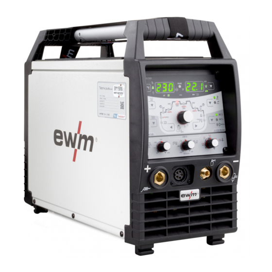
Machine description – quick overview Front view Machine description – quick overview Front view Figure 4-1 Item Symbol Description Carrying handle Machine control, see the relevant control operating instructions Connection socket, welding torch control cable > see 5.2.1.1 chapter Connection socket, "+" welding current •... -
Page 14: Rear View
Machine description – quick overview Rear view Rear view Figure 4-2 Item Symbol Description Main switch, machine on/off Cooling air outlet Machine feet Connection socket, 19-pole Remote control connection 8-pole connection socket Cooling unit control lead G¼” connecting nipple Shielding gas connection on the pressure regulator. 4-pole connection socket Cooling unit voltage supply Mains connection cable >... -
Page 15: Design And Function
Design and function Transport and installation Design and function WARNING Risk of injury from electric shock! Contact with live parts, e.g. welding current sockets, is potentially fatal! • Follow safety instructions on the opening pages of the operating instructions. • Commissioning may only be carried out by persons who have the relevant expertise of working with arc welding machines! •... -
Page 16: Workpiece Lead, General
Design and function Transport and installation 5.1.3 Workpiece lead, general CAUTION Risk of burning due to incorrect welding current connection! If the welding current plugs (machine connections) are not locked or if the workpiece connection is contaminated (paint, corrosion), these connections and leads can heat up and cause burns when touched! •... -
Page 17: Welding Torch Cooling System
Design and function Transport and installation 5.1.5 Welding torch cooling system 5.1.5.1 Welding torch cooling unit connection Read and observe the documentation to all system and accessory components! Figure 5-2 Item Symbol Description 8-pole connection socket Cooling unit control lead 4-pole connection socket Cooling unit voltage supply Cooling module... -
Page 18: Notes On The Installation Of Welding Current Leads
Design and function Transport and installation 5.1.6 Notes on the installation of welding current leads Incorrectly installed welding current leads can cause faults in the arc (flickering). Lay the workpiece lead and hose package of power sources without HF igniter (MIG/MAG) for as long and as close as possible in parallel. -
Page 19: Stray Welding Currents
Design and function Transport and installation 5.1.6.1 Stray welding currents WARNING Risk of injury due to stray welding currents! Stray welding currents can destroy protective earth conductors, damage machines and electronic devices and cause overheating of components, leading to fire. •... -
Page 20: Mains Configuration
Design and function TIG welding 5.1.7.1 Mains configuration The machine may only be connected to a one-phase system with two conductors and an earthed neutral conductor. Figure 5-7 Legend Item Designation Colour code Outer conductor brown Neutral conductor blue Protective conductor green-yellow •... -
Page 21: Connection Variant, Welding Torch Control Cable
Design and function TIG welding • Insert the welding current plug on the welding torch into the welding current connection socket and lock by turning to the right. • Remove yellow protective cap on G¼ connecting nipple. • Screw welding torch shielding gas connection tightly onto the G¼" connection nipple. •... -
Page 22: Connecting The Shielding Gas Supply
Design and function TIG welding 5.2.2.1 Connecting the shielding gas supply • Place the shielding gas cylinder into the relevant cylinder bracket. • Secure the shielding gas cylinder using a securing chain. Figure 5-10 Item Symbol Description Pressure regulator Shielding gas cylinder Output side of the pressure regulator Cylinder valve •... -
Page 23: Mma Welding
Design and function MMA welding MMA welding 5.3.1 Connecting the electrode holder and workpiece lead CAUTION Risk of crushing and burns! When changing stick electrodes there is a risk of crushing and burns! • Wear appropriate and dry protective gloves. •... -
Page 24: Remote Control
Design and function Remote control Remote control The remote controls are operated on the 19-pole remote control connection socket (analogue). 5.4.1 RT1 19POL Functions • Infinitely adjustable welding current (0% to 100%) depending on the preselected main current on the welding machine. 5.4.2 RTG1 19POL Functions... -
Page 25: Voltage Reducing Device
Design and function Voltage reducing device Voltage reducing device Only machine variants with the (VRD/AUS/RU) code are equipped with a voltage reduction device (VRD). The VRD is used for increased safety, especially in hazardous environments such as shipbuilding, pipe construction or mining. A VRD is mandatory in some countries and required by many on-site safety instructions for power sources. - Page 26 Design and function Interfaces for automation Item Signal shape Designation Output Connection for cable screen (PE) Output Current flowing signal I>0, galvanically isolated (max. +- 15V/100mA) Output Reference voltage for potentiometer 10V (max. 10mA) Input Control voltage specification for main current, 0–10V (0V = I /10V = Input Control voltage specification for secondary current, 0–10V (0V =...
-
Page 27: Maintenance, Care And Disposal
Maintenance, care and disposal General Maintenance, care and disposal General DANGER Risk of injury due to electrical voltage after switching off! Working on an open machine can lead to fatal injuries! Capacitors are loaded with electrical voltage during operation. Voltage remains present for up to four minutes after the mains plug is removed. -
Page 28: Maintenance Work, Intervals
A periodic test according to IEC 60974-4 "Periodic inspection and test" has to be carried out. In addition to the regulations on testing given here, the relevant local laws and regulations must also be observed. For more information refer to the "Warranty registration" brochure supplied and our information regarding warranty, maintenance and testing at www.ewm-group.com! 099-000239-EW501 18.05.2017... -
Page 29: Disposing Of Equipment
In addition to this, returns are also possible throughout Europe via EWM sales partners. Meeting the requirements of RoHS We, EWM AG in Mündersbach, Germany, hereby confirm that all products which we supply to you and that are subject to the RoHS directive comply with RoHS requirements (also see applicable EC directives on the Declaration of Conformity on your machine). -
Page 30: Rectifying Faults
Rectifying faults Checklist for rectifying faults Rectifying faults All products are subject to rigorous production checks and final checks. If, despite this, something fails to work at any time, please check the product using the following flowchart. If none of the fault rectification procedures described leads to the correct functioning of the product, please inform your authorised dealer. -
Page 31: Vent Coolant Circuit
Rectifying faults Vent coolant circuit Unstable arc Material inclusions in the tungsten electrode due to contact with filler material or workpiece Regrind or replace the tungsten electrode Incompatible parameter settings Check settings and correct if necessary Pore formation ... -
Page 32: Technical Data
Technical data Tetrix 230 Technical data Performance specifications and guarantee only in connection with original spare and replacement parts! Tetrix 230 Setting range Welding current 3 A–230 A 3 A–180 A Welding voltage 10.1 V–19.2 V 20.2 V–27.2 V Duty cycle (DC) at 40 °C 40% DC 230 A 180 A... -
Page 33: Tetrix 230 Ac/Dc
Technical data Tetrix 230 AC/DC Tetrix 230 AC/DC Setting range Welding current 3 A–230 A 3 A–180 A 5 A–230 A Welding voltage 10.1 V–19.2 V 20.2 V–27.2 V Duty cycle (DC) at 40 °C 230 A 180 A 40% DC 60% DC 200 A 150 A... -
Page 34: Accessories
Accessories Remote controls and accessories Accessories Performance-dependent accessories like torches, workpiece leads, electrode holders or intermediate hose packages are available from your authorised dealer. Remote controls and accessories Type Designation Item no. RTF1 19POL 5 M Foot-operated remote control current with 094-006680-00000 connection cable RT1 19POL... -
Page 35: Overview Of Ewm Branches
Appendix A Overview of EWM branches Appendix A 10.1 Overview of EWM branches 099-000239-EW501 18.05.2017...
Need help?
Do you have a question about the Tetrix 230 DC Smart 2.0 puls TM and is the answer not in the manual?
Questions and answers