
Subscribe to Our Youtube Channel
Related Manuals for EWM Tetrix 200 Smart puls 5P TG


Summary of Contents for EWM Tetrix 200 Smart puls 5P TG
- Page 1 Operating instructions Welding machine Tetrix 200 Smart puls 5P TG Tetrix 200 Smart puls 8P TG 099-000227-EW501 16.01.2015 Register now! For your benefit Jetzt Registrieren und Profitieren! www.ewm-group.com...
- Page 2 +49 2680 181-0. A list of authorised sales partners can be found at www.ewm-group.com. Liability relating to the operation of this equipment is restricted solely to the function of the equipment. No other form of liability, regardless of type, shall be accepted.
-
Page 3: Table Of Contents
Contents Notes on the use of these operating instructions Contents 1 Contents ..............................3 2 Safety instructions ..........................6 Notes on the use of these operating instructions ................6 Explanation of icons ........................7 General ............................8 Transport and installation ......................12 2.4.1 Ambient conditions ....................... - Page 4 Contents Notes on the use of these operating instructions TIG pulses – non-latched operation .............. 41 5.7.7.8 5.7.7.9 TIG pulses - latched operation ..............41 5.7.8 TIG activArc welding ..................... 42 5.7.9 Welding torch (operating variants) ................43 5.7.9.1 Tap torch trigger (tapping function) ............... 43 5.7.10 Torch mode and up/down speed setting ..............
- Page 5 Contents Notes on the use of these operating instructions 10.1 Overview of EWM branches ......................77 099-000227-EW501 16.01.2015...
-
Page 6: Safety Instructions
Safety instructions Notes on the use of these operating instructions Safety instructions Notes on the use of these operating instructions DANGER Working or operating procedures which must be closely observed to prevent imminent serious and even fatal injuries. • Safety notes include the "DANGER" keyword in the heading with a general warning symbol. •... -
Page 7: Explanation Of Icons
Safety instructions Explanation of icons Explanation of icons Symbol Description Correct Wrong Press Do not press Turn Switch Switch off machine Switch on machine ENTER ENTER (enter the menu) ENTER NAVIGATION NAVIGATION (Navigating in the menu) EXIT EXIT (Exit the menu) Time display (example: wait 4s/press) Interruption in the menu display (other setting options possible) Tool not required/do not use... -
Page 8: General
Safety instructions General General DANGER Electromagnetic fields! The power source may cause electrical or electromagnetic fields to be produced which could affect the correct functioning of electronic equipment such as IT or CNC devices, telecommunication lines, power cables, signal lines and pacemakers. •... - Page 9 Safety instructions General WARNING Smoke and gases! Smoke and gases can lead to breathing difficulties and poisoning. In addition, solvent vapour (chlorinated hydrocarbon) may be converted into poisonous phosgene due to the ultraviolet radiation of the arc! • Ensure that there is sufficient fresh air! •...
- Page 10 Safety instructions General CAUTION Obligations of the operator! The respective national directives and laws must be observed for operation of the machine! • National implementation of the framework directive (89/391/EWG), as well as the associated individual directives. • In particular, directive (89/655/EWG), on the minimum regulations for safety and health protection when staff members use equipment during work.
- Page 11 Safety instructions General CAUTION EMC Machine Classification In accordance with IEC 60974-10, welding machines are grouped in two electromagnetic compatibility classes - See 8 Technical data chapter: Class A machines are not intended for use in residential areas where the power supply comes from the low-voltage public mains network.
-
Page 12: Transport And Installation
Safety instructions Transport and installation Transport and installation WARNING Incorrect handling of shielding gas cylinders! Incorrect handling of shielding gas cylinders can result in serious and even fatal injury. • Observe the instructions from the gas manufacturer and in any relevant regulations concerning the use of compressed air! •... -
Page 13: Ambient Conditions
Safety instructions Transport and installation 2.4.1 Ambient conditions CAUTION Installation site! The machine must not be operated in the open air and must only be set up and operated on a suitable, stable and level base! • The operator must ensure that the ground is non-slip and level, and provide sufficient lighting for the place of work. -
Page 14: Intended Use
3.1.1.1 activArc The EWM activArc process, thanks to the highly dynamic controller system, ensures that the power supplied is kept virtually constant in the event of changes in the distance between the welding torch and the weld pool, e.g. during manual welding. Voltage losses as a result of a shortening of the distance between the torch and molten pool are compensated by a current rise (ampere per volt - A/V), and vice versa. -
Page 15: Documents Which Also Apply
Warranty NOTE For more information refer to the "Warranty registration" brochure supplied and our information regarding warranty, maintenance and testing at www.ewm-group.com! 3.2.2 Declaration of Conformity The designated machine conforms to EC Directives and standards in terms of its design and construction: •... -
Page 16: Machine Description - Quick Overview
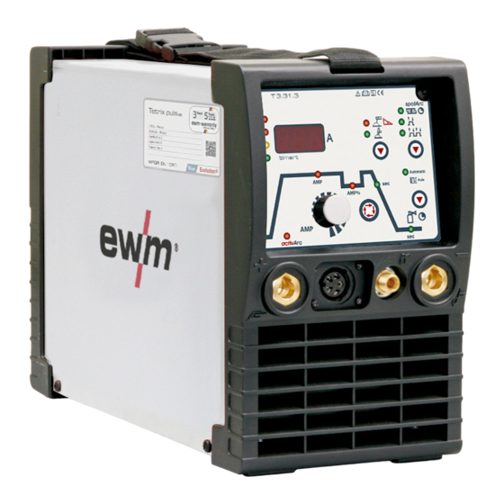
Machine description – quick overview Front view Machine description – quick overview Front view NOTE The maximum possible machine configuration is given in the text description. If necessary, the optional connection may need to be retrofitted- See 9.2 Options chapter. Figure 4-1 Item Symbol Description... -
Page 17: Rear View
Machine description – quick overview Rear view Rear view Figure 4-2 Item Symbol Description Ignition type changeover switch- See 5.7.6 Arc ignition chapter Liftarc (contact ignition) HF ignition Main switch, machine on/off Mains connection cable - See 5.6 Mains connection chapter Cooling air inlet G¼”... -
Page 18: Machine Control - Operating Elements
Machine description – quick overview Machine control – Operating elements Machine control – Operating elements Figure 4-3 Item Symbol Description Error/status indicators Collective interference signal light Water deficiency signal light (welding torch cooling) Excess temperature signal light safety sign signal light Three-figure LED display Welding parameter display - See 5.7.4 Welding data display chapter. - Page 19 Machine description – quick overview Machine control – Operating elements Item Symbol Description Main current (TIG) / pulse current Main current (MMA) I min to I max (1 A increments) I min to I max (1 A increments) AMP% Secondary current (TIG) / pulse pause current Setting range 1 % to 100 % (1 % increments).
-
Page 20: Design And Function
Design and function General Design and function General WARNING Risk of injury from electric shock! Contact with live parts, e.g. welding current sockets, is potentially fatal! • Follow safety instructions on the opening pages of the operating instructions. • Commissioning may only be carried out by persons who have the relevant expertise of working with arc welding machines! •... -
Page 21: Workpiece Lead, General
Design and function Workpiece lead, general Workpiece lead, general CAUTION Risk of burns due to incorrect connection of the workpiece lead! Paint, rust and dirt on the connection restrict the power flow and may lead to stray welding currents. Stray welding currents may cause fires and injuries! •... -
Page 22: Transport And Installation
Design and function Transport and installation Transport and installation WARNING Risk of accident due to improper transport of machines that may not be lifted! Do not lift or suspend the machine! The machine can fall down and cause injuries! The handles and brackets are suitable for transport by hand only! •... -
Page 23: Notes On The Installation Of Welding Current Leads
Design and function Notes on the installation of welding current leads Notes on the installation of welding current leads NOTE Incorrectly installed welding current leads can cause faults in the arc (flickering). Lay the workpiece lead and hose package of power sources without HF igniter (MIG/MAG) for as long and as close as possible in parallel. - Page 24 Design and function Notes on the installation of welding current leads NOTE Use an individual welding lead to the workpiece for each welding machine! Figure 5-3 NOTE Fully unroll welding current leads, torch hose packages and intermediate hose packages. Avoid loops! Always keep leads as short as possible! Lay any excess cable lengths in meanders.
-
Page 25: Mains Connection
Design and function Mains connection Mains connection DANGER Hazard caused by improper mains connection! An improper mains connection can cause injuries or damage property! • Only use machine with a plug socket that has a correctly fitted protective conductor. • If a mains plug must be fitted, this may only be carried out by an electrician in accordance with the relevant national provisions or regulations! •... -
Page 26: Tig Welding
Design and function TIG welding TIG welding 5.7.1 Welding torch and workpiece line connection NOTE Prepare welding torch according to the welding task in hand (see operating instructions for the torch). Figure 5-6 Item Symbol Description Welding torch Welding torch hose package Connection socket, "-"... -
Page 27: Torch Connection Options And Pin Assignments
Design and function TIG welding 5.7.1.1 Torch connection options and pin assignments Figure 5-7 5.7.2 Shielding gas supply (shielding gas cylinder for welding machine) WARNING Incorrect handling of shielding gas cylinders! Incorrect handling of shielding gas cylinders can result in serious and even fatal injury. •... -
Page 28: Connecting The Shielding Gas Supply
Design and function TIG welding 5.7.2.1 Connecting the shielding gas supply • Place the shielding gas cylinder into the relevant cylinder bracket. • Secure the shielding gas cylinder using a securing chain. Figure 5-8 Item Symbol Description Pressure regulator Shielding gas cylinder Output side of the pressure regulator Cylinder valve •... -
Page 29: Setting The Shielding Gas Quantity
Design and function TIG welding 5.7.2.2 Setting the shielding gas quantity CAUTION Electric shocks! When setting the shielding gas quantity, high voltage ignition pulses or open circuit voltage are applied at the welding torch; these can lead to electric shocks and burning on contact. -
Page 30: Select Welding Task
Design and function TIG welding 5.7.3 Select welding task NOTE No changes can be made to the basic welding parameters during the welding process. The welding task is selected using the buttons on the machine control on the welding machine. Signal lights (LED) display the welding parameter selection. -
Page 31: Expert Menu (Tig)
Design and function TIG welding 5.7.5 Expert menu (TIG) The expert menu includes functions and parameters which are either not set on the machine control, or which do not require regular setting. ENTER EXIT NAVIGATION Figure 5-10 Display Setting/selection Expert menu Gas pre-flow time Setting range: 0.0 s to 20.0 s (0.1 s increments) Ignition current... -
Page 32: Arc Ignition
Design and function TIG welding 5.7.6 Arc ignition 5.7.6.1 HF ignition Figure 5-11 The arc is started without contact from high-voltage ignition pulses. a) Position the welding torch in welding position over the workpiece (distance between the electrode tip and workpiece should be approx. 2-3mm). b) Press the torch trigger (high voltage ignition pulses ignite the arc). -
Page 33: Function Sequences/Operating Modes
Design and function TIG welding 5.7.7 Function sequences/operating modes The parameters for the function sequence are set using the “Select welding parameters” button and the “Welding parameter setting” rotary dial. Figure 5-13 Item Symbol Description Select welding parameters button This button is used to select the welding parameters depending on the welding process and operating mode used. -
Page 34: Non-Latched Mode
Design and function TIG welding 5.7.7.2 Non-latched mode Figure 5-14 1st cycle: • Press and hold torch trigger 1. • The gas pre-flow time elapses. • HF ignition pulses jump from the electrode to the workpiece, the arc ignites. • The welding current flows and immediately assumes the value set for the ignition current I start •... -
Page 35: Latched Mode
Design and function TIG welding 5.7.7.3 Latched mode Figure 5-15 Step 1 • Press torch trigger 1, the gas pre-flow time elapses. • HF ignition pulses jump from the electrode to the workpiece, the arc ignites. • Welding current flows and immediately assumes the ignition current value set (search arc at minimum setting). -
Page 36: Spotarc
Design and function TIG welding 5.7.7.4 spotArc This process is suitable for tack welding or joint welding of metal sheets made from steel and CrNi alloys up to a thickness of approximately 2.5 mm. Metal sheets of different thicknesses can also be welded on top of one another. - Page 37 Design and function TIG welding Figure 5-16 As an example the process is shown with HF ignition. Arc ignition with lift arc is also possible, however- See 5.7.6 Arc ignition chapter. Sequence: • Press and hold torch trigger 1. • The gas pre-flow time elapses.
-
Page 38: Spotmatic
Design and function TIG welding 5.7.7.5 Spotmatic NOTE This function must be enabled before use- See 5.12 Machine configuration menu chapter. In contrast to the spotarc operating mode, the arc ignites not by pressing the torch trigger as is usual, but by shortly touching the tungsten electrode against the workpiece. - Page 39 Design and function TIG welding Figure 5-17 As an example the process is shown with HF ignition. Arc ignition with lift arc is also possible, however- See 5.7.6 Arc ignition chapter. Select the process activation type- See 5.12 Machine configuration menu chapter. Up- and down-slope times possible for long setting range of the spot time (0.01 s - 20.0 s) only.
-
Page 40: Non-Latched Operation, Version C
Design and function TIG welding 5.7.7.6 Non-latched operation, version C Figure 5-18 1st cycle • Press torch trigger 1, the gas pre-flow time elapses. • HF ignition pulses jump from the electrode to the workpiece, the arc ignites. • Welding current flows and immediately adopts the ignition current value set (search arc at minimum setting). -
Page 41: Automated Pulses
Design and function TIG welding 5.7.7.7 Automated pulses NOTE The machines have an integrated pulse device. With pulses, the machine switches back and forth between the pulse current (main current) and pause current (secondary current). The automated pulses are used with tacking and spot welding of workpieces in particular. An oscillation in the molten pool is produced by the current-dependent pulse frequency and balance, which positively influences the ability to bridge the air gap. -
Page 42: Tig Activarc Welding
5.7.8 TIG activArc welding The EWM activArc process, thanks to the highly dynamic controller system, ensures that the power supplied is kept virtually constant in the event of changes in the distance between the welding torch and the weld pool, e.g. during manual welding. Voltage losses as a result of a shortening of the distance between the torch and molten pool are compensated by a current rise (ampere per volt - A/V), and vice versa. -
Page 43: Welding Torch (Operating Variants)
Design and function TIG welding 5.7.9 Welding torch (operating variants) Different torch versions can be used with this machine. Functions on the operating elements, such as torch triggers (TT), rockers or potentiometers, can be modified individually via torch modes. Explanation of symbols for operating elements: Symbol Description Press torch trigger... -
Page 44: 5.7.10 Torch Mode And Up/Down Speed Setting
Design and function TIG welding 5.7.10 Torch mode and up/down speed setting The user has the modes 1 to 6 and modes 11 to 16 available. Modes 11 to 16 include the same function options as 1 to 6, but without tapping function for the secondary current. The function options in the individual modes can be found in the tables for the corresponding torch types. -
Page 45: Standard Tig Torch (5-Pole)
Design and function TIG welding 5.7.10.1 Standard TIG torch (5-pole) Standard torch with one torch trigger: Diagram Operating Explanation of symbols elements BRT1 = Torch trigger 1 (welding current on/off; secondary current via tapping function) Functions mode Operating elements Welding current On/Off (factory-set) Secondary current (Latched mode) Standard torch with two torch triggers:... - Page 46 Design and function TIG welding Standard torch with one rocker (MG rocker, two torch triggers) Diagram Operating Explanation of symbols elements BRT 1 = torch trigger 1 BRT 2 = torch trigger 2 Functions mode Operating elements Welding current On/Off Secondary current (factory-set) Secondary current (tapping mode) / (latched mode)
-
Page 47: Tig Up/Down Torch (8-Pole)
Design and function TIG welding 5.7.10.2 TIG up/down torch (8-pole) Up/down torch with one torch trigger Diagram Operating Explanation of symbols elements TT 1 = torch trigger 1 Functions Mode Operating elements Welding current on/off Secondary current (tapping mode) / (latched mode) (factory- set) Increase welding current, infinite adjustment (up function) - Page 48 Design and function TIG welding Up/down torch with two torch triggers Diagram Operating Explanation of symbols elements TT 1 = torch trigger 1 (left) TT 2 = torch trigger 2 (right) Functions Mode Operating elements Welding current on/off Secondary current Secondary current (tapping mode) / (latched mode) (factory- set)
-
Page 49: Potentiometer Torch (8-Pole)
Design and function TIG welding 5.7.10.3 Potentiometer torch (8-pole) NOTE The welding machine needs to be configured for operation with a potentiometer torch- See 5.7.10.4 Configuring the TIG potentiometer torch connection chapter. Potentiometer torch with one torch trigger: Diagram Operating Explanation of symbols elements BRT 1 = torch trigger 1... -
Page 50: 5.7.10.4 Configuring The Tig Potentiometer Torch Connection
Design and function TIG welding 5.7.10.4 Configuring the TIG potentiometer torch connection DANGER Risk of injury due to electrical voltage after switching off! Working on an open machine can lead to fatal injuries! Capacitors are loaded with electrical voltage during operation. Voltage remains present for up to four minutes after the mains plug is removed. -
Page 51: 5.7.10.5 Setting The First Increment
Design and function TIG welding 5.7.10.5 Setting the first increment Figure 5-24 ENTER EXIT NAVIGATION Figure 5-25 Display Setting/selection Exit the menu Exit Torch configuration menu Set welding torch functions Setting the first increment Setting: 1 to 20 (factory setting 1) NOTE This function is only available when using up/down torches in modes 4 and 14! 099-000227-EW501... -
Page 52: Mma Welding
Design and function MMA welding MMA welding CAUTION Risk of being crushed or burnt. When replacing spent or new stick electrodes • Switch off machine at the main switch • Wear appropriate safety gloves • Use insulated tongs to remove spent stick electrodes or to move welded workpieces and •... -
Page 53: Select Welding Task
Design and function MMA welding 5.8.2 Select welding task Operating Action Result element MMA welding process selection. Signal light lights up in green. Set welding current. If necessary, the pulse function can be enabled as well. Signal light lights up in green. 5.8.3 Arcforce Shortly before the electrode threatens to stick, the arcforcing device sets an increased current designed... -
Page 54: Hotstart Current And Hotstart Time
Design and function MMA welding 5.8.5 Hotstart current and Hotstart time The hotstart device improves the ignition of the stick electrodes using an increased ignition current. a) = Hotstart time b) = Hotstart current Welding current Time NOTE ENTER (enter the menu) •... -
Page 55: Mma Pulse Welding In The Vertical Up Position (Pf)
Design and function MMA welding 5.8.6 MMA pulse welding in the vertical up position (PF) Welding characteristics: • Especially suitable for root welding • Fine-flaked weld surface with a TIG look for final passes • Less finishing work thanks to less spatter •... - Page 56 Design and function MMA welding ENTER EXIT Autom atic Puls NAVIGATION Figure 5-30 Display Setting/selection Expert menu Hotstart current Hotstart current setting Hotstart time Hotstart time setting Pulse current Setting range in percent: 1% to 200%, dependent on main current, 142% ex works Pulse pause current Setting range in percent: 1% to 200%, dependent on main current, 82% ex works Alternating current balance (AC)
-
Page 57: Remote Control
Design and function Remote control Remote control NOTE Insert the remote control control cable into the 19-pole connection socket for remote control connection and lock. 5.9.1 Manual remote control RT1 19POL Functions • Infinitely adjustable welding current (0% to 100%) depending on the preselected main current on the welding machine. -
Page 58: Foot-Operated Remote Control Rtf1 19Pol 5 M / Rtf2 19Pol 5 M
Design and function Remote control 5.9.6 Foot-operated remote control RTF1 19POL 5 M / RTF2 19POL 5 M Functions • Infinitely adjustable welding current (0% to 100%) depending on the preselected main current on the welding machine. • Start/stop welding operation (TIG) ActivArc welding is not possible in combination with the foot-operated remote control. -
Page 59: Ramp Function Foot-Operated Remote Control Rtf 1 / Rtf 2
Design and function Remote control 5.9.6.1 Ramp function foot-operated remote control RTF 1 / RTF 2 ENTER EXIT NAVIGATION Figure 5-32 Display Setting/selection Exit the menu Exit Machine configuration (part two) Settings for machine functions and parameter display Ramp function Remote control RTF 1 The ramp function can be switched on and off Switch on Switching on machine function... -
Page 60: Pc Interface
Design and function PC interface 5.10 PC interface CAUTION Equipment damage or faults may occur if the PC is connected incorrectly! Not using the SECINT X10USB interface results in equipment damage or faults in signal transmission. The PC may be destroyed due to high frequency ignition pulses. •... -
Page 61: 5.11.1 Remote Control Connection Socket, 19-Pole
Design and function Interfaces for automation 5.11.1 Remote control connection socket, 19-pole Figure 5-33 Pos. Signal shape Designation Output Connection for cable screen (PE) Output Current flows signal I>0, galvanically isolated (max. +- 15V/100mA) Output Reference voltage for potentiometer 10V (max. 10mA) Input Control value specification for main current, 0-10V (0V = I , 10V =... -
Page 62: Machine Configuration Menu
Design and function Machine configuration menu 5.12 Machine configuration menu The machine menu includes basic functions such as torch modes, display settings and the service menu. 5.12.1 Selecting, changing and saving parameters NOTE ENTER (enter the menu) • Switch off machine at the main switch •... - Page 63 Design and function Machine configuration menu EXIT ENTER NAVIGATION Figure 5-34 099-000227-EW501 16.01.2015...
- Page 64 Design and function Machine configuration menu Display Setting/selection Exit the menu Exit Torch configuration menu Set welding torch functions Torch mode (factory setting 1) Up-/Down speed Increase value = rapid current change (factory setting 10) Reduce value = slow current change Setting the first increment Setting: 1 to 20 (factory setting 1) Machine configuration...
- Page 65 Design and function Machine configuration menu Display Setting/selection Setting process activation • on = Separate process activation: The welding process has to be reactivated for every arc ignition by pressing the torch trigger. • off = Permanent process activation: The welding process is activated by pressing the torch trigger once. The following arc ignitions are initiated by shortly touching the tungsten electrode against the workpiece.
- Page 66 Design and function Machine configuration menu Display Setting/selection Reset (reset to factory settings) • off = aus (factory setting) • CFG = Reset the values in the machine configuration menu • CPL = Complete reset of all values and settings The reset is performed when leaving the menu (EXIT).
-
Page 67: Maintenance, Care And Disposal
Maintenance, care and disposal General Maintenance, care and disposal DANGER Do not carry out any unauthorised repairs or modifications! To avoid injury and equipment damage, the unit must only be repaired or modified by specialist, skilled persons! The warranty becomes null and void in the event of unauthorised interference. •... -
Page 68: Annual Test (Inspection And Testing During Operation)
In addition to this, returns are also possible throughout Europe via EWM sales partners. Meeting the requirements of RoHS We, EWM AG Mündersbach, hereby confirm that all products supplied by us which are affected by the RoHS Directive, meet the requirements of the RoHS (Directive 2011/65/EU). -
Page 69: Rectifying Faults
Rectifying faults Checklist for rectifying faults Rectifying faults All products are subject to rigorous production checks and final checks. If, despite this, something fails to work at any time, please check the product using the following flowchart. If none of the fault rectification procedures described leads to the correct functioning of the product, please inform your authorised dealer. - Page 70 Rectifying faults Checklist for rectifying faults Unstable arc Material inclusions in the tungsten electrode due to contact with filler material or workpiece Regrind or replace the tungsten electrode Incompatible parameter settings Check settings and correct if necessary Pore formation ...
-
Page 71: Error Messages (Power Source)
Rectifying faults Error messages (power source) Error messages (power source) NOTE A welding machine error is indicated by the collective fault signal lamp (A1) lighting up and an error code (see table) being displayed in the machine control display. In the event of a machine error, the power unit shuts down. - Page 72 Rectifying faults Error messages (power source) Error message Possible cause Remedy Err 20 Coolant Check coolant level and refill if necessary • The flow quantity of the torch coolant Check coolant level in the reverse cooler • has fallen below the permissible Check coolant lines for leaks and kinks minimum ->...
-
Page 73: Resetting Welding Parameters To The Factory Settings
Rectifying faults Resetting welding parameters to the factory settings Resetting welding parameters to the factory settings NOTE All customised welding parameters that are stored will be replaced by the factory settings. ENTER EXIT NAVIGATION Figure 7-1 Display Setting/selection Exit the menu Exit Service menu Modifications to the service menu may only be carried out by authorised maintenance... -
Page 74: Display Machine Control Software Version
Rectifying faults Display machine control software version Display machine control software version NOTE The query of the software versions only serves to inform the authorised service staff! ENTER EXIT NAVIGATION Figure 7-2 Display Setting/selection Exit the menu Exit Service menu Modifications to the service menu may only be carried out by authorised maintenance staff! Software version query (example) -
Page 75: Technical Data
Technical data Tetrix 200 Smart Technical data NOTE Performance specifications and guarantee only in connection with original spare and replacement parts! Tetrix 200 Smart Welding current setting range 5A-200 A 5A-150 A Welding voltage setting range 10.2 V-18.0 V 20.2 V-26.0 V Duty cycle at 25 °C 25% DC 200 A... -
Page 76: Accessories
Accessories Remote controls and accessories Accessories NOTE Performance-dependent accessories like torches, workpiece leads, electrode holders or intermediate hose packages are available from your authorised dealer. Remote controls and accessories Type Designation Item no. RTF1 19POL 5 M Foot-operated remote control current with 094-006680-00000 connection cable RTF2 19POL 5 M... - Page 77 Appendix A Overview of EWM branches Appendix A 10.1 Overview of EWM branches 099-000227-EW501 16.01.2015...
Need help?
Do you have a question about the Tetrix 200 Smart puls 5P TG and is the answer not in the manual?
Questions and answers