Motorola APX 8000XE User Manual
Hide thumbs
Also See for APX 8000XE:
- User manual (108 pages) ,
- Instruction manual (91 pages) ,
- Basic operation (39 pages)

Related Manuals for Motorola APX 8000XE


Summary of Contents for Motorola APX 8000XE
- Page 1 APX TWO-WAY RADIOS MODEL 1 APX 8000XE USER GUIDE JANUARY 2021 *MN002667A01* MN002667A01-AR © 2021 Motorola Solutions, Inc. All rights reserved...
-
Page 2: Table Of Contents
MN002667A01-AR Contents Contents List of Tables....................... 8 Software Version......................9 Chapter 1: Read Me First..................10 1.1 Notations Used in This Manual....................10 1.2 Radio Care..........................11 1.2.1 Cleaning Your Radio....................12 1.2.2 Cleaning the External Surface of the Radio.............12 1.2.3 Radio Service and Repair..................12 1.3 Battery Recycling and Disposal..................... - Page 3 MN002667A01-AR Contents 4.1.1 Fuel Gauge Icons.....................23 4.1.2 HAZLOC Battery Type Detection................23 4.2 LED Indications........................24 4.3 Status Icons........................... 24 4.4 Intelligent Lighting Indicators....................27 4.5 Alert Tones ........................... 27 4.6 Display Color Change On Channel..................29 Chapter 5: General Radio Operation..............30 5.1 Selecting a Zone........................30 5.2 Selecting a Radio Channel....................
- Page 4 MN002667A01-AR Contents 6.5.1 Turning Scan On or Off....................39 6.5.2 Making a Dynamic Priority Change (Conventional Scan Only)........40 6.5.3 Deleting a Nuisance Channel.................. 40 6.5.4 Restoring a Nuisance Channel................40 6.6 Call Alert Paging........................40 6.6.1 Receiving a Call Alert Page..................41 6.6.2 Sending a Call Alert Page..................41 6.7 Recent Calls..........................
- Page 5 ® Wireless Technology..........60 6.19.1 Turning On Bluetooth ....................60 6.19.2 Turning Off the Bluetooth..................60 6.19.3 Pairing with Low Frequency-Motorola Proximity Pairing (LF-MPP) Feature..61 6.19.4 Standard Pairing Feature..................61 6.19.4.1 Searching and Pairing the Bluetooth Device..........62 6.19.4.2 Turning On Bluetooth Visibility..............62 6.19.4.3 Receiving Pairing Request from other Devices........63...
- Page 6 MN002667A01-AR Contents 6.19.9 Responder Alert Sensors..................64 6.19.9.1 Holster Sensor..................65 6.19.9.2 Weapon Fired Sensor................65 6.19.9.3 Vest Pierced Sensor................65 6.19.9.4 Disabling the Sensor................65 6.20 ASTRO 25 (P25) Programming Over Project 25 (POP25)..........66 6.21 Voice Announcement ......................66 6.22 Site Selectable Alerts (ASTRO 25 Trunking)...............67 6.23 Wi-Fi............................
- Page 7 Declaration of Compliance for the Use of Distress and Safety Frequencies....... 81 Technical Parameters for Interfacing External Data Sources............81 Limited Warranty.......................82 MOTOROLA SOLUTIONS COMMUNICATION PRODUCTS............. 82 I. WHAT THIS WARRANTY COVERS AND FOR HOW LONG:..........82 II. GENERAL PROVISIONS:....................... 83 III.
-
Page 8: List Of Tables
MN002667A01-AR List of Tables List of Tables Table 1: LED Indications ........................24 Table 2: ViQi Virtual Partner Queries ....................35 Table 3: Emergency Operation Scenarios .....................43 Table 4: VHF Marine Channel List ......................79... -
Page 9: Software Version
MN002667A01-AR Software Version Software Version All the features described in the following sections are supported by the software version R22.00.00 or later. Contact your system administrator for more details of all the supported features. -
Page 10: Chapter 1: Read Me First
MN002667A01-AR Chapter 1: Read Me First Chapter 1 Read Me First This User Guide covers the basic operation of the radio. However, your dealer or system administrator may have customized your radio for your specific needs. Check with your dealer or system administrator for more information. -
Page 11: Radio Care
• Elastomer seals used in portable radios age with time and environmental exposure. To ensure the waterseal integrity of the radio, Motorola Solutions recommends that radios be checked annually as a preventive measure. The disassembly, test, and reassembly procedures along with necessary test equipment are available in the Service Manual. -
Page 12: Cleaning Your Radio
Radio Service and Repair Proper repair and maintenance procedures ensure efficient operation and long life of this radio. A Motorola Solutions maintenance agreement provides expert service to keep the radio and all other communication equipment in perfect operating condition. A nationwide service organization is provided by Motorola Solutions to support maintenance services. -
Page 13: Battery Recycling And Disposal
Chapter 1: Read Me First Battery Recycling and Disposal In the U.S. and Canada, Motorola Solutions participates in the nationwide Call2Recycle program for battery collection and recycling. Many retailers and dealers participate in this program. For the location of the drop-off facility closest to you, go to http://www.call2recycle.org/... -
Page 14: Over-The-Air Rekeying
1.4.7 P25 Digital Vehicular Repeater System Motorola Solutions offers an MSI Certified APX compatible, third party, P25 Digital Vehicular Repeater System (DVRS) that provides low-cost portable radio coverage in areas where only mobile radio coverage is available and portable radio coverage is either intermittent or non-existent. -
Page 15: What Your Dealer/System Administrator Can Tell You
MN002667A01-AR Chapter 1: Read Me First What Your Dealer/System Administrator Can Tell You If the radio is to be operated in extreme temperatures (less than -30 °C or more than +60 °C), check with your system administrator for the correct radio settings. You can consult your dealer or system administrator about the following: •... -
Page 16: Chapter 2: Preparing Your Radio For Use
NOTICE: When charging a battery attached to a radio, the radio must be turned off. Procedure: To charge the battery, place the battery (with or without the radio) in a Motorola Solutions- approved charger. The LED on the charger indicates the charging progress, see the Charger User Guide. -
Page 17: Attaching The Antenna
You can view the status of the battery if the radio is using an IMPRES 2 battery. NOTICE: User is notified if radio detects non-Motorola Solutions battery upon powering up, charging, or removing from the charger. This feature is applicable for IMPRES and Non-IMPRES battery. -
Page 18: Using The Carry Holder
MN002667A01-AR Chapter 2: Preparing Your Radio for Use 4 Press the top of the cover downward to seat it in the slot. 5 Tighten by rotating the thumbscrew clockwise by hand. Using the Carry Holder Procedure: 1 Position the radio within the carry holder with the main speaker facing outward. 2 Slide the radio down into the carry holder until it clicks in place. -
Page 19: Chapter 3: Radio Controls
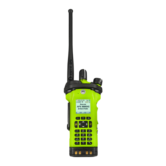
MN002667A01-AR Radio Controls Chapter 3 Radio Controls This chapter explains the buttons and functions to control the radio. Radio Parts and Controls Antenna Top (Orange) Button This button is usually programmed as the Emergency button. -
Page 20: Programmable Features
MN002667A01-AR Chapter 3: Radio Controls Accessory Connector 16-Position Select Knob This knob is usually programmed for channel selection. On/Off/Volume Control Knob Rotate clockwise until you hear a click to turn on the radio. Rotate counterclockwise until you hear a click to turn off the radio. Rotate clockwise to increase the volume. -
Page 21: Assignable Radio Functions
MN002667A01-AR Chapter 3: Radio Controls 3.2.1 Assignable Radio Functions Bluetooth On/Off Toggles Bluetooth between on and off. Bluetooth Audio Reroute Toggles the audio route between the radio speaker or the Remote Speaker Microphone and the Bluetooth headset. Bluetooth Headset PTT Keys up the Bluetooth Headset microphone. -
Page 22: Assignable Settings Or Utility Functions
MN002667A01-AR Chapter 3: Radio Controls Request-To-Talk (Conventional Only) Notifies the dispatcher that you want to send a voice call. Scan Short press – Toggles the scan function between on and off. Long press – Enables Scan List Programming and selects the scan list for editing. Secure Transmission Select Toggles secure transmission between on and off. -
Page 23: Chapter 4: Status Indicators
MN002667A01-AR Status Indicators Chapter 4 Status Indicators This section explains the status indicators of the radio. Battery Charge Status Your radio indicates the battery charge status through LED, sounds, and the fuel gauge icon on the display. You can also check the battery charge status by using the menu entry. If you press the PTT button when your battery is low, the LED blinks red and you hear a short, high- pitched tone. -
Page 24: Led Indications
MN002667A01-AR Chapter 4: Status Indicators • A repetitive tone sounds • LED blinks RED continuously NOTICE: The radio alerts you when NNTN8921and NNTN8930 batteries are attached to the radio as these batteries are not supported. The radio is not HAZLOC-certified and resets if these batteries are used. - Page 25 MN002667A01-AR Chapter 4: Status Indicators Icon Description For IMPRES 2 battery operation only – the icon shown indicates the charge remaining in the battery. For all battery operation – the icon blinks when the battery is low. The number of bars displayed represents the received signal strength for the current site (trunking only).
- Page 26 MN002667A01-AR Chapter 4: Status Indicators Icon Description Basic Zone Bank 2 Radio is in Zone 4. Radio is in Zone 5. Radio is in Zone 6. Enhanced Zone Bank Contains Zone 1, Zone 2, and Zone 3, Contains Zone 4, Zone 5, and Zone 6, until Contains Zone 7, Zone 8, and Zone 9, until...
-
Page 27: Intelligent Lighting Indicators
MN002667A01-AR Chapter 4: Status Indicators Intelligent Lighting Indicators This feature temporarily changes the backlight of the top display screen to help signal that a radio event has occurred. This feature temporarily changes the display backlight color and the alert text background color of the radio to help signal that a radio event has occurred. - Page 28 MN002667A01-AR Chapter 4: Status Indicators You Hear Tone Name Heard Man Down Entry When radio initiates Man Down mode. Long, Low- Time-Out Timer Timed After time out. Pitched Tone Talk Prohibit/PTT In- (When PTT button is pressed) transmissions are not al- hibit lowed.
-
Page 29: Display Color Change On Channel
MN002667A01-AR Chapter 4: Status Indicators You Hear Tone Name Heard Gurgle Dynamic Regrouping (When PTT button is pressed) a dynamic ID has been received. Talk Permit (When PTT button is pressed) is verifying with the sys- tem for accepting its transmissions. Unique, New Message When a new message is received. -
Page 30: Chapter 5: General Radio Operation
MN002667A01-AR Chapter 5: General Radio Operation Chapter 5 General Radio Operation This chapter explains the general operations of your radio. Selecting a Zone When and where to use:A zone is a group of channels. Procedure: • Select a zone using the preprogrammed Zone (3-Position A/B/C) switch: a. -
Page 31: Receiving And Responding To A Private Call (Trunking Only)
MN002667A01-AR Chapter 5: General Radio Operation • For Trunking system, the display shows the caller alias or ID. Procedure: 1 Hold the radio vertically 1 to 2 inches (2.5 to 5.0 cm) from your mouth. 2 Press the PTT button to respond to the call. The LED lights up solid red. -
Page 32: Making A Talkgroup Call
MN002667A01-AR Chapter 5: General Radio Operation 5.4.1 Making a Talkgroup Call Procedure: 1 Turn the 16-Position Select Channel Knob to select the channel with the desired talkgroup. 2 Hold the radio vertically 1 to 2 inches (2.5 to 5.0 cm) from your mouth. 3 Press the PTT button to make the call. -
Page 33: Switching Between Repeater Or Direct Operation Button
MN002667A01-AR Chapter 5: General Radio Operation If the target radio does not respond before the time out, the display shows NO ANSR. 3 Press and hold the PTT button to talk. Release the PTT button to listen. 4 Press the preprogrammed Private Call button to return to the home screen. Switching Between Repeater or Direct Operation Button The Repeater Operation increases the radio coverage area by connecting with other radios through a repeater. - Page 34 MN002667A01-AR Chapter 5: General Radio Operation When and where to use:Your radio may be preprogrammed to receive Private-Line ® (PL) calls. Procedure: 1 Momentarily press the Monitor button to listen for activity. The Carrier Squelch indicator appears on the display. 2 Press and hold the Monitor button to set continuous monitor operation.
-
Page 35: Chapter 6: Advanced Features
MN002667A01-AR Advanced Features Chapter 6 Advanced Features This chapter explains the operations of the features available in your radio. ViQi ViQi is a virtual assistant that helps you manage your radio and perform information lookups using voice commands. This feature is purpose-built for public safety and is active when you press the assigned ViQi button on the radio, Remote Speaker Microphone (RSM), or compatible mobile microphone. -
Page 36: Using Viqi Virtual Partner
MN002667A01-AR Chapter 6: Advanced Features Query Examples "Can I get my exact location?" "Am I still at the <Location>?" NOTICE: ViQi will ask for more information to complete the query. Target Location "Where is <Unit Name>? "Tell me where <Unit Name> is. NOTICE: ViQi will ask for more information to complete the query. -
Page 37: Making A Selective Call
MN002667A01-AR Chapter 6: Advanced Features 6.2.1.2 Making a Selective Call Prerequisites:Your radio must be preprogrammed for you to use this feature. Procedure: 1 Press the preprogrammed Selective Call button to dial the preprogrammed ID. 2 Hold the radio vertically 1 to 2 inches (2.5 to 5.0 cm) from your mouth. 3 Press and hold the PTT button to start the Selective Call. -
Page 38: Classification Of Regrouped Radios
MN002667A01-AR Chapter 6: Advanced Features 6.2.3.1 Classification of Regrouped Radios The dispatcher can classify regrouped radios into Select Enabled or Select Disabled categories. Select Enabled Select-enabled radios are free to change to any available channel, including the dynamic- regrouping channel, once you have selected the dynamic-regrouping position. Select Disabled Select-disabled radios cannot change channels while dynamically regrouped. -
Page 39: Intelligent Priority Scan
MN002667A01-AR Chapter 6: Advanced Features 6.4.1 Intelligent Priority Scan Intelligent Priority Scan feature allows you to add or delete conventional channels and trunking talkgroups from multiple system into the priority scan lists. When the radio locks onto a channel in the Intelligent Priority Scan list, radio scans for higher priority member within the same Trunking or Conventional system. -
Page 40: Making A Dynamic Priority Change (Conventional Scan Only)
MN002667A01-AR Chapter 6: Advanced Features 6.5.2 Making a Dynamic Priority Change (Conventional Scan Only) When and where to use: While the radio is scanning, the dynamic priority change feature allows you to temporarily change any channel in a scan list (except for the Priority-One channel) to the Priority-Two channel. This change remains in effect until scan is turned off. -
Page 41: Receiving A Call Alert Page
MN002667A01-AR Chapter 6: Advanced Features Depending on how your radio is programmed, if there is no answer after the maximum ring time or when you press the PTT button for an Enhanced Private Call, the radio automatically sends a call alert page. -
Page 42: In-Call User Alert
MN002667A01-AR Chapter 6: Advanced Features Radio displays Audio Saved momentarily. Radio plays the saved call automatically if call saving is successful. A tone sounds if call saving is not successful. • Playback the saved calls using the preprogrammed Record Playback button: a. -
Page 43: Special Considerations For Emergency Operation
MN002667A01-AR Chapter 6: Advanced Features Non-Tactical/Revert for Conventional System The radio reverts to the preprogrammed emergency channel to send an alarm and/or make an emergency call. Non-Tactical/Revert for Trunking System The radio reverts to the preprogrammed emergency talkgroup (trunking system) or channel (conventional system) to send an alarm and/or make an emergency call. -
Page 44: Exiting Emergency As Supervisor (Trunking Only)
MN002667A01-AR Chapter 6: Advanced Features 6.9.4 Exiting Emergency as Supervisor (Trunking Only) Radios configured as Supervisor are able to cancel emergency mode of other radios. The dispatch console must be preprogrammed to use this feature. Check with your dealer or system administrator for more information on dispatch console supporting this feature. -
Page 45: Sending An Emergency Call (Trunking Only)
MN002667A01-AR Chapter 6: Advanced Features 6.9.6 Sending an Emergency Call (Trunking Only) When and where to use:This feature gives your radio priority access to a talkgroup. Procedure: 1 Press the preprogrammed Emergency button. One of the following scenarios occurs: • The display shows EMERGNCY and the current zone or channel. -
Page 46: Sending An Emergency Alarm With Emergency Call
MN002667A01-AR Chapter 6: Advanced Features 6.9.8 Sending an Emergency Alarm with Emergency Call When and where to use: This feature gives your radio priority access on a channel for conventional system, and to a talkgroup for trunking system. Procedure: 1 Press the preprogrammed Emergency button. If successful, the display shows EMERGNCY on the current zone and channel. -
Page 47: Sending A Silent Emergency Alarm
MN002667A01-AR Chapter 6: Advanced Features If unsuccessful, a tone sounds to indicate that the selected channel does not support emergency and rejects to launch emergency mode. 2 The microphone remains active for the hot mic time specified in your radio's codeplug programming. -
Page 48: Entering Fireground Zone Channel (Conventional)
MN002667A01-AR Chapter 6: Advanced Features It consists of central components that provide on-scene and inbuilding radio coverage, and enhanced personnel accountability and monitoring: • Your APX portable radios • Incident Management Software • Command Terminal • Radio Frequency (RF) Modem (Conventional Only) •... -
Page 49: Responding To Evacuation Indicator
MN002667A01-AR Chapter 6: Advanced Features 5 Release the PTT button to receive. You hear a Transmit End Tone. 6.10.2 Responding to Evacuation Indicator When and where to use:The Incident Commander can trigger one of sixteen Tactical Alerts from the Command Terminal. These alerts can target individuals or groups of users within the Fireground Communication System. -
Page 50: Using Tps Emergency Transmission
MN002667A01-AR Chapter 6: Advanced Features 6.12.2 Using TPS Emergency Transmission When and where to use: The following are two important alert tones designed for this feature. Emergency Beacon During Emergency if the TPS radio user pushes the Emergency button, the radio sounds a Beacon at the maximum volume of the radio at radio’s internal speaker and it is not adjustable. -
Page 51: Testing The Man Down Feature
MN002667A01-AR Chapter 6: Advanced Features Man Down Enhanced Your radio also supports Man Down Enhanced where it plays an alert tone for a preprogrammed period. This tone is louder than the preprogrammed minimum level or the current level of the speaker and it acts as a beacon that helps to find the radio. -
Page 52: Secure Operations
MN002667A01-AR Chapter 6: Advanced Features 6.14 Secure Operations Secure radio operation provides the highest commercially available level of voice security on both trunked and conventional channels. By default, the radio automatically enters the encrypted environment without having to manually select or clear the secure transmission. -
Page 53: Multikey Feature
MN002667A01-AR Chapter 6: Advanced Features Procedure: 1 Attach the KVL to your radio. The display shows KEYLOAD and all other radio functions, except for power down, backlight, and volume, are locked out. NOTICE: If the Multi-system Over-the-Air Rekeying feature is in use, the ASTRO profile name is displayed below KEYLOAD. -
Page 54: Requesting An Over-The-Air Rekey
6.14.3.5 MDC OTAR (Conventional Only) This feature allows you to view or define the Motorola Data Communications (MDC) Over-the-Air Rekeying (OTAR) features. It is applied only when operating in secure encrypted mode. In addition to Rekey Requests, OTAR transmissions include Delayed Acknowledgments, and Power-up Acknowledgments. -
Page 55: Radio Inhibit
MN002667A01-AR Chapter 6: Advanced Features Random FM Noise Canceller (Flutter Fighter) Reduces the unwanted effects of random FM noise pulses caused by channel fading under high Signal-to-Noise (S/N) conditions such as in a moving transportation. The fading effects, heard as audio pops and clicks, are canceled without affecting the desired audio signal. -
Page 56: Location Feature In Emergency Mode
MN002667A01-AR Chapter 6: Advanced Features • Lat/Long(DDM) • Lat/Long(DMS) • UTM/UCS • SLD99 • MGRS NOTICE: When you send your location to another radio, the receiving radio displays the location in its selected format. 6.16.3 Location Feature in Emergency Mode When the Emergency feature is activated, the radio exits the Location menu and returns to the Home screen for you to view the channel that triggers the emergency signal. -
Page 57: Mission Critical Geofence
MN002667A01-AR Chapter 6: Advanced Features Once the radio is connected, you hear a dynamic regroup tone, the radio display shows <DYNAMIC channel> with the temporary green color intelligent backlight and you hear a Voice Announcement. NOTICE: When the radio loses the GPS signal, the GPS icon blinks and the radio sounds two high- pitched tones repetitively to indicate that the GPS has failed to operate. -
Page 58: Exiting Mission Critical Geofence
MN002667A01-AR Chapter 6: Advanced Features The radio then connects to the designated talkgroup. The radio displays the talkgroup alias and dynamic regroup tone sounds. The transmit power level changes and the radio shows a direct text message content without any user operation. NOTICE: The availability of the Voice Announcement (VA), TMS display, Intelligent Backlight, and Transmit Power Level alerts depend on your radio configuration. -
Page 59: Smartconnect
NOTICE: This feature must be preprogrammed by a qualified radio technician. Contact your system administrator for more information. Your radio can connect through a fixed Wi-Fi access point in buildings or in-vehicle Broadband modem such as the following modems: • Motorola Solutions VML750 • Sierra Wireless MP70 • Sierra Wireless GX450... -
Page 60: Changing The Current Site
Wireless Technology ® This feature allows your radio to extend its functionality by connecting to external proprietary Motorola Solutions accessories. Use Motorola Solutions proprietary Mission Critical Wireless (MCW) devices with APX radios during Mission Critical operations as other Bluetooth devices may or may not meet the mission critical standard. -
Page 61: Pairing With Low Frequency-Motorola Proximity Pairing (Lf-Mpp) Feature
Obstacles that can cause an obstruction in the line-of-sight include trees, buildings, mountains, cars, and others. For high degree of reliability, Motorola Solutions recommends to NOT separate the radio and the accessory. At the fringe areas of reception, both voice and tone quality will start to sound "garbled" or "broken". To correct this problem, simply position the accessory and radio closer to each other (within the 10 meter defined range) to re-establish clear audio reception. -
Page 62: Searching And Pairing The Bluetooth Device
When and where to use:Bluetooth Search in Bluetooth Standard Pairing method is used to scan for other Bluetooth devices nearby. It is set to turn off by default. The radio only search for HSP devices and Motorola Solutions MCW & OCW accessories. Radio filters out other profiles. -
Page 63: Receiving Pairing Request From Other Devices
MN002667A01-AR Chapter 6: Advanced Features 6.19.4.3 Receiving Pairing Request from other Devices Procedure: Turn on your radio Bluetooth Visible mode. Your radio automatically accept the request and pair with any request received from other device. 6.19.4.4 Turning Off Bluetooth Visibility Prerequisites:Ensure that Bluetooth Visibility is turned on. -
Page 64: Adjusting The Volume Of The Radio From Bluetooth Audio Device
MN002667A01-AR Chapter 6: Advanced Features 6.19.7 Adjusting the Volume of the Radio from Bluetooth Audio Device Prerequisites:Ensure that the Bluetooth audio device is connected to the radio. When and where to use: Your radio can only control the volume of MCW and OCW Bluetooth enabled audio device. If the radio is paired with other Bluetooth enabled audio device, its volume is independent from the APX radio. -
Page 65: Holster Sensor
MN002667A01-AR Chapter 6: Advanced Features 6.19.9.1 Holster Sensor Holster sensor monitors the state of the holster and allows the radio to send an over-the-air (OTA) notification whenever a gun or a taser is pulled out of the holster or put in the holster. The sensor can cache events that happen when the sensor is disconnected from the radio. -
Page 66: Astro 25 (P25) Programming Over Project 25 (Pop25)
MN002667A01-AR Chapter 6: Advanced Features • If the timer expires without an event, a tone sounds, the radio switches the sensor to enabled state, and clears the sensor status from the display. • If the preprogrammed Sensor button is long-pressed, the OTA sensor notification is enabled. 6.19.9.4.2 Disabling the Sensor Permanently Procedure:... -
Page 67: Site Selectable Alerts (Astro 25 Trunking)
MN002667A01-AR Chapter 6: Advanced Features 6.22 Site Selectable Alerts (ASTRO 25 Trunking) A Site Selectable Alert (SSA) is an Intelligent Lighting indicator with audio alert sent to radios at sites to notify the users when there is a special situation that they need to be aware of. Your radio supports up to 250 site aliases. -
Page 68: Utilities
MN002667A01-AR Chapter 6: Advanced Features 6.24 Utilities This chapter explains the operations of the utility functions available in your radio. 6.24.1 Using the Flip Display When and where to use:This feature allows you to flip the content of the top display upside down. It is particularly useful when you would like to read the top display while the radio is still in the carry holder attached to your belt. -
Page 69: Controlling The Display Backlight
MN002667A01-AR Chapter 6: Advanced Features Power level Low enables a shorter transmitting distance and to conserve power. Power level High enables a longer transmitting distance. Procedure: • Use the preprogrammed Transmit Power Level switch to toggle the power level between low and high power. -
Page 70: Using The Time-Out Timer
MN002667A01-AR Chapter 6: Advanced Features 6.24.7 Using the Time-Out Timer When and where to use:This feature turns off the transmitter of your radio. You cannot transmit longer than the preset timer setting. If you attempt to do so, the radio automatically stops your transmission, and you hear a talk-prohibit tone. -
Page 71: Using The Pl Defeat Feature
MN002667A01-AR Chapter 6: Advanced Features 6.24.9 Using the PL Defeat Feature This feature allows you to override any coded squelch that preprogrammed to a channel. The radio also unmutes to any digital activity on a digital channel. When this feature is active, the Carrier Squelch status indicator is displayed. -
Page 72: Transmit Inhibit
MN002667A01-AR Chapter 6: Advanced Features 6.24.12 Transmit Inhibit This feature allows you to stops all transmission including voice and data. The radio can receive messages but not able to reply the acknowledgment request of the received message. This feature is available for APCO 25 trunking, Type II trunking and Conventional operations for all APX radios. -
Page 73: Chapter 7: Accessories
MN002667A01-AR Accessories Chapter 7 Accessories Not all accessories are FCC certified to operate with all radio models and/or bandsplits. Refer to the radio price pages for a list of FCC certified accessories or contact your sales representative for accessory compatibility. Visit http://www.motorolasolutions.com to know more about the accessories supported by this radio. -
Page 74: Legal And Compliance Statements
Furthermore, Motorola Solutions reserves the right to change any products to improve readability, function, or design. Motorola Solutions does not assume any liability arising out of the applications or use of any product or circuit described herein; nor does it cover any license under its patent rights, nor the rights of others. -
Page 75: Declaration Of Conformity
Name: Motorola Solutions, Inc. Address: 2000 Progress Pkwy, Schaumburg, IL 60196-1078, U.S.A. Phone Number: 1-800-927-2744 Hereby declares that APX 8000XE conforms to FCC Part 15, subpart B, section 15.107(a), 15.107(d), and section 15.109(a) Class B Digital Device As a personal computer peripheral, this device complies with Part 15 of the FCC Rules. Operation is... -
Page 76: Important Safety Information
Before using the radio, read the RF Energy Exposure and Product Safety Guide for Portable Two-Way Radios which contains important operating instructions for safe usage and RF energy awareness and control for Compliance with applicable standards and Regulations. For a list of Motorola Solutions-approved antennas, batteries, and other accessories, visit the following website: http://www.motorolasolutions.com Under Industry Canada regulations, this radio transmitter may only operate using an antenna of a type and maximum (or lesser) gain approved for the transmitter by Industry Canada. -
Page 77: Applying For Canadian License
Applying for Canadian License The operation of your Motorola Solutions radio is subject to the Radio communications Act and must comply with rules and regulations of the Federal Government's department of Industry Canada. -
Page 78: Maritime Radio Use In The Vhf Frequency Range
MN002667A01-AR Maritime Radio Use in the VHF Frequency Range Maritime Radio Use in the VHF Frequency Range Special Channel Assignments Emergency Channel If you are in imminent and grave danger at sea and require emergency assistance, use VHF Channel 16 to send a distress call to nearby vessels and the United States Coast Guard. Transmit the following information, in this order: 1 “MAYDAY, MAYDAY, MAYDAY.”... -
Page 79: Table 4: Vhf Marine Channel List
MN002667A01-AR Maritime Radio Use in the VHF Frequency Range in the semiduplex mode on the two frequency channels specified in the table below. NOTICE: Simplex channels 3, 21, 23, 61, 64, 81, 82, and 83 cannot be lawfully used by the general public in US waters. - Page 80 MN002667A01-AR Maritime Radio Use in the VHF Frequency Range 156.075 160.675 156.125 160.725 156.175 160.775 156.225 160.825 156.275 160.875 156.325 160.925 67** 156.375 156.375 156.425 156.425 156.475 156.475 156.575 156.575 156.625 – 156.675 156.675 156.725 156.725 77** 156.875 – 156.925 161.525 156.975 161.575...
-
Page 81: Declaration Of Compliance For The Use Of Distress And Safety Frequencies
MN002667A01-AR Maritime Radio Use in the VHF Frequency Range Declaration of Compliance for the Use of Distress and Safety Frequencies The radio equipment does not employ a modulation other than the internationally adopted modulation for maritime use when it operates on the distress and safety frequencies specified in RSS-182 Section 7.3. -
Page 82: Limited Warranty
Product Accessories One (1) Year MOTOROLA SOLUTIONS, at its option, will at no charge either repair the Product (with new or reconditioned parts), replace it (with a new or reconditioned Product), or refund the purchase price of the Product during the warranty period provided it is returned in accordance with the terms of this warranty. -
Page 83: Ii. General Provisions
MN002667A01-AR Limited Warranty made only at the designated MOTOROLA SOLUTIONS repair depot. Local services are not included. MOTOROLA SOLUTIONS will pay for outbound shipping via MOTOROLA SOLUTIONS'S normal shipping methods. II. GENERAL PROVISIONS: This warranty sets forth the full extent of MOTOROLA SOLUTIONS'S responsibilities regarding the Product. -
Page 84: Vi. Patent And Software Provisions
1 that MOTOROLA SOLUTIONS will be notified promptly in writing by such purchaser of any notice of such claim,... -
Page 85: Viii. For Australia Only
You are also entitled to be compensated for any other reasonably foreseeable loss or damage from a failure in the goods or service. If you have any queries, please call Motorola Solutions Australia at 1800 457 439. You may also visit our website: https://www.motorolasolutions.com/en_xa/support.html... -
Page 86: Glossary
Automatic Registration Service ASTRO 25 Motorola Solutions standard for wireless digital trunked communications. ASTRO conventional Motorola Solutions standard for wireless analog or digital conventional communications. Autoscan A feature that allows the radio to automatically scan the members of a scan list. Bluetooth Bluetooth is an open wireless technology standard for exchanging data over short distances from fixed and mobile devices with high levels of security. - Page 87 MN002667A01-AR Glossary Channel A group of characteristics, such as transmit/receive frequency pairs, radio parameters, and encryption encoding. Control Channel In a trunking system, one of the channels that is used to provide a continuous, two-way/data- communications path between the central controller and all radios on the system. Conventional Typically refers to radio-to-radio communications, sometimes through a repeater.
- Page 88 It can also trigger Emergency Alarm the Post-Alert Timer is not cancelled. Mission Critical Wireless. Motorola Solutions Digital Communications. Monitor Check channel activity by pressing the Monitor button. If the channel is clear, you hear static. If the channel is in use, you hear conversation.
- Page 89 MN002667A01-AR Glossary Non-tactical/revert The user will talk on a preprogrammed emergency channel. The emergency alarm is sent out on this same channel. Operation Critical Wireless. Over-The-Air Rekeying Allows the dispatcher to remotely reprogram the encryption keys in the radio. Page A one-way alert with audio and/or display messages.
- Page 90 MN002667A01-AR Glossary Synchronous Serial Interface (SSI) DSP interface to peripherals that consists of a clock signal line, a frame synchronization signal line, and a data line. Standby An operating condition whereby the radio’s speaker is muted but still continues to receive data. Status Calls Pre-defined text messages that allow the user to send a conditional message without talking.
Need help?
Do you have a question about the APX 8000XE and is the answer not in the manual?
Questions and answers