Motorola APX 8000XE User Manual
Hide thumbs
Also See for APX 8000XE:
- Instruction manual (91 pages) ,
- User manual (90 pages) ,
- Basic operation (39 pages)
Table of Contents
Advertisement
Quick Links
Advertisement
Table of Contents

Related Manuals for Motorola APX 8000XE


Summary of Contents for Motorola APX 8000XE
-
Page 3: Table Of Contents
Contents Documentation Copyrights...13 Declaration of Conformity......6 Disclaimer........14 Important Safety Information..8 Getting Started....... 15 How to Use This Guide........15 Notations Used in This Manual......15 Software Version......9 Additional Performance Enhancement..15 Notice to Users (FCC and Industry ASTRO 25 Enhanced Data....15 Canada)............9 Dynamic System Resilience (DSR).. - Page 4 Attaching the Antenna........19 Selecting a Zone..........39 Removing and Attaching the Accessory Selecting a Radio Channel......39 Connector Cover........20 Receiving and Responding to a Radio Call... 39 Attaching the Belt Clip........21 Receiving and Responding to a Turning On the Radio........22 Talkgroup Call........39 Adjusting the Volume........23 Receiving and Responding to a...
- Page 5 Viewing a Scan List......46 Using TPS Normal Transmission..54 Viewing and Changing the Priority Using TPS Emergency Status..........46 Transmission......... 54 Scan.............. 46 Man Down............. 55 Turning Scan On or Off.......46 Pre-Alert Timer........57 Making a Dynamic Priority Change Post-Alert Timer........57 (Conventional Scan Only)....46 Radio Alerts When Man Down Deleting a Nuisance Channel.....
- Page 6 Checking the Wi-Fi Configuration Bluetooth Drop Timer......70 and Status of the Radio....78 Pairing with Low Frequency- Utilities............79 Motorola Proximity Pairing (LF- Using the Flip Display......79 MPP) Feature........ 71 Selecting a Basic Zone Bank....79 Radio Indications of Lost Bluetooth Selecting an Enhanced Zone Bank..79...
- Page 7 Radio Care............ 86 Cleaning Your Radio......87 Limited Warranty......100 Proper Ways to Handle the Radio..87 Radio Service and Repair....87 MOTOROLA COMMUNICATION Battery Care..........88 PRODUCTS........... 100 Battery Charge Status......88 I. WHAT THIS WARRANTY COVERS Battery Recycling and Disposal..89 AND FOR HOW LONG:......
-
Page 8: Declaration Of Conformity
Name: Motorola Solutions, Inc. Address: 1303 East Algonquin Road, Schaumburg, IL 60196-1078, U.S.A. Phone Number: 1-800-927-2744 Hereby declares that the product: Model Name: APX 8000XE conforms to the following regulations: FCC Part 15, subpart B, section 15.107(a), 15.107(d) and section 15.109(a) English... - Page 9 Class B Digital Device As a personal computer peripheral, this device complies with Part 15 of the FCC Rules. Operation is subject to the following two conditions: 1 This device may not cause harmful interference, and 2 This device must accept any interference received, including interference that may cause undesired operation. Note: This equipment has been tested and found to comply with the limits for a Class B digital device, pursuant to part 15 of the FCC Rules.
-
Page 10: Important Safety Information
Radios which contains important operating instructions for safe usage and RF energy awareness and control for Compliance with applicable standards and Regulations. For a list of Motorola-approved antennas, batteries, and other accessories, visit the following website: http://www.motorolasolutions.com/APX Under Industry Canada regulations, this radio... -
Page 11: Software Version
• This device must accept any interference received, including interference that may cause undesired operation. • Changes or modifications made to this device, not expressly approved by Motorola, could void the authority of the user to operate this equipment. English... -
Page 12: Consignes De Sécurité Importantes
Cet émetteur radio a été approuvé par Industrie Canada pour utilisation avec une antenne approuvée Cette radio ne doit être utilisée qu'à des fins par Motorola offrant le gain maximal autorisé et professionnelles. Avant d'utiliser la radio, lisez le l'impédance requise pour le type d'antenne indiqué. Il... -
Page 13: Version Logicielle
Motorola, peuvent annuler le droit de l'utilisateur à Version logicielle utiliser cet équipement. Toutes les fonctions décrites dans les sections suivantes sont prises en charge par la version R14.50.00 ou les versions ultérieures du logiciel de la radio. Pour obtenir davantage de renseignements à propos des fonctions prises en charge, adressez-vous à... -
Page 14: Computer Software Copyrights
Motorola. Furthermore, the purchase of Motorola products shall not be deemed to grant either directly or by implication, estoppel, or otherwise, any license under the copyrights, patents or patent... -
Page 15: Documentation Copyrights
No duplication or distribution of this document or any portion thereof shall take place without the express written permission of Motorola. No part of this manual may be reproduced, distributed, or transmitted in any form or by any means, electronic or mechanical, for any purpose without the express written permission of Motorola. -
Page 16: Disclaimer
However, no responsibility is assumed for inaccuracies. Furthermore, Motorola reserves the right to make changes to any products herein to improve readability, function, or design. Motorola does not assume any liability arising out of the applications or use of any product or circuit described herein;... -
Page 17: Getting Started
damage to the equipment if not carefully Getting Started observed. Note: How to Use This Guide An operational procedure, practice, or condition and so on, which is essential to This User Guide covers the basic operation of the emphasize. APX Portables. However, your dealer or system administrator may Additional Performance Enhancement have customized your radio for your specific needs. -
Page 18: Crosstalk Prevention
A maximum of four talkgroups SecureNet allows user to perform secured can be supported when Vote Scan channels are communications on an Analog or Motorola Data being used. Communication (MDC) channel. The MDC Over-the- Smart PTT is supported with this enhancement as... -
Page 19: What Your Dealer/System Administrator Can Tell You
Note: User Selectable Talkgroups are not compatible with this Conventional Talkgroup Enhancement. What Your Dealer/System Administrator Can Tell You Check with your dealer or system administrator for the correct radio settings, if the radio is to be operated in extreme temperatures (less than -30 °C or more than +60 °C). -
Page 20: Preparing Your Radio For Use
Accessories on page Note: When charging a battery attached to a radio, turn the radio off to ensure a full charge. To charge the battery, place the battery (with or without the radio) in a Motorola-approved charger. English... -
Page 21: Attaching The Antenna
2 To remove the battery, squeeze the release Attaching the Antenna latches at the bottom of the battery until the battery releases from the radio and remove the Ensure the radio is turned off before attaching the battery from the radio. antenna. -
Page 22: Removing And Attaching The Accessory Connector Cover
Removing and Attaching the Accessory Connector Cover The accessory connector is on the antenna side of the radio. It is used to connect accessories to the radio. Note: To prevent damage to the connector, shield it with the connector cover when not in use. 1 To remove the accessory connector cover, rotate the thumbscrew counterclockwise until it... -
Page 23: Attaching The Belt Clip
Attaching the Belt Clip 1 Align the grooves of the belt clip with those of the radio and press upward until you hear a click to attach the belt clip. 2 Rotate and lift the connector cover to disengage it from the radio. -
Page 24: Turning On The Radio
Turning On the Radio • If the power-up test is successful, you see 1 Rotate the On/Off/Volume Control Knob momentary on the radio display, followed by clockwise until you hear a click. the Home screen. • If the power-up test is successful, you see a splash screen on the radio display, followed by the Home screen. -
Page 25: Adjusting The Volume
Note: Adjusting the Volume If the radio fails to power-up after repeating a few times, record the Ensure the radio is power on and the main speaker is ERROR XX/YY code and contact your pointed towards you for increased loudness and dealer. -
Page 26: Identifying Radio Controls
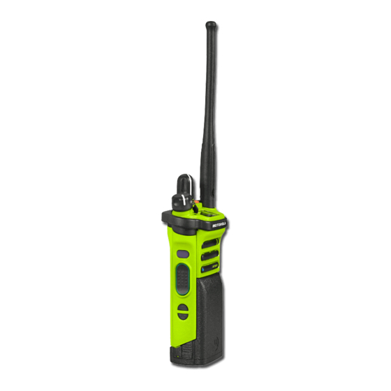
Identifying Radio Controls Radio Parts and Controls Antenna Top (Orange) Button Accessory Connector 16–Position Select Knob English... -
Page 27: Programmable Features
On/Off/Volume Control Knob Programmable Features 3–Position A/B/C Switch Any reference in this manual to controls that are preprogrammed means that a qualified radio Belt Clip technician must use the radio programming software Battery Latch to assign a feature to a control. Your dealer can program the programmable buttons as shortcuts to radio functions or preset channels/ 2–Position Concentric Switch... - Page 28 Remote Speaker Microphone cancels an emergency alarm or and Bluetooth headset. call. Bluetooth Keys up the Bluetooth Headset Internet Protocol Display the Internet Protocol Headset PTT microphone. Address (IP) address, device name and status of the radio. Bluetooth Clear Allows you to clear all pairing information for Bluetooth.
- Page 29 separately programmed buttons Secure Toggles the Secure for four different features. Transmission On or Off when Transmission Select the Secure/Clear Strapping Private Line Overrides any coded squelch (Conventional fields is set to Select for the Defeat (DPL or PL) that is and Trunking) current channel and when the (Conventional...
-
Page 30: Assignable Settings Or Utility Functions
banks (A, B ... X or Y) of 3 Accessing the Preprogrammed Functions zones. You can access various radio functions through a Assignable Settings or Utility Functions short or long press of the relevant programmable buttons. Locks or unlocks the Controls Lock programmable buttons, Push-To-Talk (PTT) Button... - Page 31 • While a call is in progress, the PTT button allows the radio to transmit to other radios in the call. Press and hold down PTT button to talk. Release the PTT button to listen. The microphone is activated when the PTT button is pressed. •...
-
Page 32: Identifying Status Indicators
Received Signal Strength Indicator Identifying Status Indicators (RSSI) Status Icons The number of bars displayed repre- sents the received signal strength for the Selected icons are also shown on the first row of the current site, for trunking only. The more 112 x 32 pixel top monochrome display screen of stripes in the icon, the stronger the sig- your radio. - Page 33 Power Level Basic Zone Bank 1 L – Radio is set at Low power. A – Radio is in Zone 1. H – Radio is set at High power. B – Radio is in Zone 2. C – Radio is in Zone 3. Scan Radio is scanning a scan list.
-
Page 34: Led Indicator
Bluetooth is currently connected to the Y – Contains Zone 73, Zone 74 and Zone 75. external Bluetooth device. Secure Operation LED Indicator On – Secure operation. The LED indicator shows the operational status of Off – Clear operation. your radio. Blinking –... - Page 35 Rapidly blinking Radio has failed the self test Blinking blue three Bluetooth is powering on or upon powering up or off. times encountered a fatal error. Slow blinking blue Radio is waiting to be paired Solid yellow Channel is busy. when no device is connected (Conventional with radio in Bluetooth.
-
Page 36: Intelligent Lighting Indicators
qualified technician to be permanently disabled. Consult your dealer for further details if you want to disable it. Intelligent Lighting Indicators This feature temporarily changes the backlight of the top display screen, and adds a color bar to the main display screen to help signal that a radio event has occurred. -
Page 37: Alert Tones
Backlight and Bar Notification When Color The radio receives a phone call. The radio receives a call alert. The radio receives a selective call. The radio enters Geofence. Alert Tones Your radio uses alert tones to inform you of the condition of your radio. The following table lists these tones and when they occur. - Page 38 You Hear Tone Name Heard Long, Low- Time-Out Timer Timed Out After time out. Pitched Tone Talk Prohibit/PTT Inhibit (When PTT button is pressed) transmissions are not allowed. Lack of Voice PTT Time out When the radio ends your call after it detected there are lack of voice for 5 seconds after the PTT is pressed and hold.
- Page 39 You Hear Tone Name Heard Central Echo When central controller has received a request from a radio. When volume is changed on a quiet channel. Long, Medium- Volume Set Pitched Tone Emergency Exit When exiting the emergency state. A Group of Me- Failsoft When the trunking system fails.
- Page 40 You Hear Tone Name Heard Talk Permit (When PTT button is pressed) is verifying with the system for ac- cepting its transmissions. Unique, Low- New Message When a new message is received. Pitched Chirp When a priority message is received. Unique, High- Priority Status Pitched Chirp...
-
Page 41: General Radio Operation
a) Rotate the preprogrammed 16–Position General Radio Operation Select Knob to the desired channel. b) Press the PTT button to transmit on the Selecting a Zone displayed zone channel. Your radio must be preprogrammed to allow you to Receiving and Responding to a Radio Call use this feature. -
Page 42: Receiving And Responding To A Private Call (Trunking Only)
• For ASTRO Conventional system, the LED lights Note: up solid yellow. The display shows the talkgroup With the inactivity timer enabled (optional), alias or ID, and the caller alias or ID. when there is no response from the receiving radio, the calling radio exits the call with Menu •... -
Page 43: Methods To Make A Radio Call
Note: • The 16-Position Select Channel Knob. With the inactivity timer enabled (optional), if Making a Talkgroup Call there is no response to the call after the timer expires, your radio exits the call with Menu To make a call to a group of users, your radio must Inactive Exit tone. -
Page 44: Switching Between Repeater Or Direct Operation Button
channel is an indication that the radio is not working Switching Between Repeater or Direct properly. This is not the case. Operation Button Digital technology quiets the transmission by The Repeater Operation increases the radio removing the noise from the signal and allows only coverage area by connecting with other radios the clear voice or data information to be heard. -
Page 45: Monitoring Conventional Mode
Monitoring Conventional Mode Your radio may be preprogrammed to receive Private- ® Line (PL) calls. 1 Momentarily press the Monitor button to listen for activity. The Carrier Squelch indicator appears on the display. 2 Press and hold the Monitor button to set continuous monitor operation. -
Page 46: Advanced Features
Responding to the Dynamic Regrouping Feature Advanced Features (Trunking Only) This feature allows the dispatcher to temporarily Advanced Call Features reassign selected radios to a particular channel where they can communicate with each other. This feature is Selective Call (ASTRO Conventional Only) typically used during special operations and is This feature allows you to receive a call from a enabled by a qualified radio technician. -
Page 47: Scan Lists
that you were using before the radio was dynamically including the dynamic-regrouping regrouped. channel, once the user has selected Requesting a Reprogram (Trunking Only) the dynamic-regrouping position. This feature allows you to notify the dispatcher when Select Select-disabled radios cannot change you want a new dynamic regrouping assignment. -
Page 48: Viewing A Scan List
in your radio. These lists must be preprogrammed by One channel, regardless of traffic on non- a qualified radio technician. priority channels. • No icon indicates that the current channel is Viewing a Scan List deleted from the scan list. Turn the 16-Position Select Knob to view the members on the list. -
Page 49: Deleting A Nuisance Channel
This change remains in effect until scan is turned off. When the radio is locked onto the channel to be Scan then reverts to the preprogrammed (original) deleted, press the preprogrammed Nuisance setting. Delete button. Making a Dynamic Priority Change via the The radio continues scanning the remaining channels preprogrammed Dynamic Priority button: in the list. -
Page 50: Receiving A Call Alert Page
Note: • Silent Emergency Alarm This feature must be preprogrammed by a Check with your dealer or system administrator for qualified radio technician. more information on the programming of this feature. Receiving a Call Alert Page Only one of the Emergency modes above can be When you receive a Call Alert page, you hear four assigned to the preprogrammed Emergency button. -
Page 51: Sending An Emergency Alarm
• The display shows EMERGENCY and the send alarm and/or make current zone or channel. You hear a short emergency call. medium-pitched tone and the LED blinks red Non-Tactical/ The radio reverts to the momentarily. Revert for preprogrammed • The radio sounds a short low-pitched tone to Trunking emergency talkgroup to indicate that the selected channel does not... -
Page 52: Sending An Emergency Alarm With Emergency Call
medium-pitched tone and the LED blinks red If successful, the display shows EMERGNCY on momentarily. the current zone and channel. You hear a short, medium-pitched tone and the LED blinks red • You hear the radio sounds a short low-pitched momentarily. -
Page 53: Sending A Silent Emergency Alarm
• Press and release the PTT button to exit the 4 Release the PTT button to end the transmission Silent Emergency Alarm mode and enter and wait for a response from the dispatcher. regular dispatch or Emergency Call mode. 5 To exit Emergency Call, press and hold the Change of Channels during Emergency preprogrammed Emergency button for about a second. -
Page 54: Emergency Find Me
Sending an Emergency Alarm on page Press the pre-programmed Emergency button to Sending an Emergency Call (Trunking transmit the EFM beacon. Only) on page 49, Sending an Emergency The receiving radio displays BEAC RX . Alarm with Emergency Call on page 50, or Sending a Silent Emergency Alarm on page Fireground (Conventional Only) -
Page 55: Entering Fireground Zone Channel
and sector are all can be configured to be seen at the • If the Fireground Zone Channel is set as Commander’s command terminal. default, but you hear a short, low-pitched tone, the display shows REG FAIL to indicate that If you have a critical situation, you can press the the command terminal does not respond to Emergency button which activates an alarm on the... -
Page 56: Responding To Evacuation Indicator
pressing the PTT button shall cancel the 4 Press and hold the PTT button to transmit. The indications and acknowledge the command LED lights up solid red while transmitting. Talk into terminal. the microphone clearly if needed. 5 Release the PTT button to receive. Tactical Public Safety (TPS) (Conventional You hear a Transmit End Tone. -
Page 57: Man Down
the radio sounds a Beacon at the Man Down maximum volume of the radio at Man Down condition is determined based upon the radio’s internal speaker and it is not radio tilt angle or a combination of radio tilt angle and adjustable. - Page 58 Note: transmitted. The Man Down Clear function is used It is recommended that an Emergency button in this phase to cancel the Man Down condition. is preprogrammed in order to allow the user to The following scenarios affect the timers: exit the emergency condition.
-
Page 59: Pre-Alert Timer
When the radio is programmed with Man Radio Alerts When Man Down Feature is Triggered Down feature, special care is required when The Man Down alert tone volume is directly related to charging the radio with a wall mounted the radio speaker volume. Ensure that the radio charger. -
Page 60: Radio Alerts When Man Down Enhanced Is Triggered
Note: and visual alert associated with the At this point the Man Down features is emergency feature. complete. Use normal Emergency procedures If the radio is programmed in Surveillance to cancel Emergency transmissions. Mode, the alert tone can be heard from the Radio Alerts When Man Down Enhanced is Triggered radio speaker. -
Page 61: Re-Initiating Man Down
(when motion sensitivity is enabled). trunked and conventional channels. Testing the Man Down Feature Unlike other forms of security, Motorola digital Enable the Emergency feature with Silent Alarm encryption provides signaling that makes it virtually disabled, but not in Surveillance Mode before running impossible for others to decode any part of an this test on the radio. -
Page 62: Selecting Secure Transmissions
Selecting Secure Transmissions Selecting Clear Transmissions Turn the preprogrammed Secure/Clear switch to Turn the preprogrammed Secure/Clear switch to the secure position. the clear position. Note: Note: If the selected channel is preprogrammed If the selected channel is preprogrammed for clear-only operation, when you press for secure-only operation, when you press the PTT button, you hear an invalid mode the PTT button, you hear an invalid mode... -
Page 63: Managing Encryption
The Secure/Clear switch only applies Multikey Feature when the radio is transmitting. This feature allows the radio to be equipped with different encryption keys and supports the DES-OFB Managing Encryption algorithm. Loading an Encryption Key There are two types: Note: Conventional The encryption keys can be tied Refer to the key-variable loader (KVL) manual... - Page 64 Requesting an Over-the-Air Rekey (ASTRO have operator-selectable key Conventional Only) erasure. Ensure that the Unique Shadow Key (USK) is loaded Erasing the Selected Encryption Keys into the radio with the key-variable loader (KVL) This feature allows you to erase all or selected before the rekey request can be sent.
- Page 65 when operating in secure encrypted mode and only Hear Clear for conventional communications. In additional to Note: Rekey Requests, OTAR transmissions include This feature must be preprogrammed by a Delayed Acknowledgements, and Power-up qualified radio technician. Check with your Acknowledgements. dealer or system administrator for more Some of the options selected may also need to be set information.
-
Page 66: Global Positioning System / Global Navigation Satellite System
buttons and strings remain the same as the Random FM Reduces the unwanted effects of legacy feature of GPS. Noise random FM noise pulses caused by Canceller channel fading under high Signal-to- The availability and accuracy of this location (Flutter Noise (S/N) conditions such as in a information (and the amount of time that it takes to Fighter) -
Page 67: Gps Performance Enhancement
your radio will not work. Such situations include but within 10 meters from your actual location, but are not limited to: sometimes farther away. • Underground locations The satellites used by the GPS feature are controlled by the U.S. government and are subject to changes •... -
Page 68: Peer-Location On The Display (Astro Conventional Only)
Peer-Location on the Display (ASTRO Conventional available. Refer to the following list for the details only) shown in the Peer-Location quick text. Consult your agent to pick the best format to configure to your This feature is only available for radio-to-radio voice radio. -
Page 69: Trunking System Controls
The PTT ID seen here is optional to be shown 2 Press the PTT button to talk, and release the on the display per requirement of usage. button to listen. Trunking System Controls Out-of-Range Radio Operating in Failsoft System When your radio goes out of the range of the system, it can no longer lock onto a control channel. -
Page 70: Site Display And Search Button
Home screen. Note: Site Display and Search Button It is recommended to use Motorola proprietary The Site Display and Site Search button allows you Mission Critical Wireless (MCW) devices with to view the name of the current site or force your APX radios during Mission Critical operations radio to change to a new one. -
Page 71: Turning On Bluetooth
If Bluetooth fails to launch, the display shows devices to re-establish a new set of pairing keys. See Pairing with Low BT ON FL. Frequency-Motorola Proximity Pairing Turning Off the Bluetooth (LF-MPP) Feature on page 71 and Standard Pairing Feature on page 73. -
Page 72: Bluetooth Drop Timer
again, they can resume the Bluetooth Re-Pair Tim- Re-Pair Timer Scenarios connection without user intervention. er Options tablish the Bluetooth Connection Re-Pair Tim- Re-Pair Timer Scenarios for a period of time depending er Options upon the Drop Timer value. If the Immediate •... -
Page 73: Pairing With Low Frequency
0 – 15 minutes, 2 To establish the Bluetooth Connection, see Pairing hours, 4 hours or 8 hours. with Low Frequency-Motorola Proximity Pairing (LF- MPP) Feature on page 71 or Standard Pairing Do note there are exceptions for Feature on page 73 . -
Page 74: Radio Indications Of Lost Bluetooth Connection
Obstacles that can cause an obstruction in the line-of- If the pairing process fails, you hear a short, low- sight include trees, buildings, mountains, cars and pitched tone. The display shows PAIRFAIL. etc. Repeat this step. It is not recommended that you leave your radio The radio tries to establish connection with the device behind and expect your accessory to work with a high once paired. -
Page 75: Standard Pairing Feature
It is set to off by default. preprogrammed buttons must be preprogrammed by a qualified radio The radio only search for HSP devices and Motorola technician. Check with your dealer or system MCW & OCW accessories. Radio filters out other administrator for more information. - Page 76 • If successful, the display shows SRCH ON Turning On Bluetooth Visibility followed by SRCH END when the radio is Turning Bluetooth visibility to on enables other pairing with a device found. The display shows Bluetooth devices to search for your radio. The <Device Name>...
-
Page 77: Turning On The Bluetooth Audio (Routing The Audio From The Radio To The Headset)
Your radio automatically accept the request and Adjusting the Volume of the Radio from Bluetooth pair with any request received from other device. Audio Device Ensure that the Bluetooth audio device is connected Turning On the Bluetooth Audio (Routing the Audio to the radio. -
Page 78: Over-The-Air Programming (Pop 25, Astro 25, Astro Conventional)
If unsuccessful, you hear the radio sounds a Note: short, low-pitched tone.The display shows CLR This feature must be preprogrammed by a qualified radio technician. Check with your FAIL. dealer or system administrator for more Note: information. If Re-Pair Timer is set to infinite and you clear Responding to the Notification of Upgrade keys on the radio, you must clear keys on all previously paired devices as well. -
Page 79: Site Selectable Alerts (Astro 25)
The two options of priority for the Voice • Change to a new channel remaining within the Announcement available are: current zone. The radio announces the current channel. High Enables the voice of the feature to announce • Press either the preprogrammed button or switch even when the radio is receiving calls. -
Page 80: Wi-Fi
When mixing SSA with received voice audio, This button must be preprogrammed by a the SSA alert is reduced in volume to ensure qualified radio technician. Check with your that the voice message is still heard clearly. dealer or system administrator for more Therefore, it is important that the SSA audio information. -
Page 81: Utilities
If the radio is Wi-Fi connected, you see a Wi-Fi Use the preprogrammed Basic Zone Bank button to toggle the position between Bank 1 and Bank 2. signal strength indicator, on the top display. The top display shows the status icons (A, B, C, D, E or F) or the zone name based on the bank and Utilities switch position selected. -
Page 82: Selecting The Power Level
Top (Orange) button before you can use this Power level Low enables a shorter transmitting feature. distance and to conserve power. Power level High enables a longer transmitting distance. 1 Press the preprogrammed EZB Up or EZB Down button to scroll the EZB up or down or press and Use the preprogrammed Transmit Power Level hold the preprogrammed EZB Up or EZB Down switch to toggle the power level between low and... -
Page 83: Locking And Unlocking The Controls
• To turn the backlight on, press any disabled or the display shows momentary VMUT ON, programmable radio controls or buttons. and you hear a short tone, indicating that the feature is enabled. Locking and Unlocking the Controls Using the Time-Out Timer You can lock the programmable buttons, switches, This feature turns off the transmitter of your radio. -
Page 84: Using Conventional Squelch Operation Features
Digital Options 2 Release the PTT button. The timer resets. One or more of the following options may be preprogrammed in your radio. Check with your dealer 3 To re-transmit, press the PTT button. or system administrator for more information. The time-out timer restarts and the LED lights up solid red. -
Page 85: Digital Ptt Id Support
One of the following scenarios occurs: When smart PTT is enabled in your radio, you cannot transmit on an active channel. • You hear any activity on the channel. If you try to transmit on an active smart-PTT channel, • The radio is muted if no activity is present. -
Page 86: Transmit Inhibit
The radio sounds alert tone when user enters or exits Mode Description this feature and also when PTT is pressed. can override the transmit-inhibit Note: state by quick-keying the radio. In Acknowledgement of any messages required other words, two PTT button from the radio is not transmitted if the Transmit presses within the preprogram- Inhibition is enabled. - Page 87 Disabling Transmit Inhibition Press the Transmit Inhibit programmable button. Note: If the user has disabled TX Inhibit via the softkey and then moves the switch to the position where TX Inhibit is enabled, the new value overwrites the menu value. The display shows Tx inhibit off.
-
Page 88: Helpful Tips
• Your radio casting has a vent port that preventive measure in order to assure the allows for pressure equalization in the watertight integrity of the radio. Motorola radio. Never poke this vent with any details the disassembly, test, and... -
Page 89: Cleaning Your Radio
Proper repair and maintenance procedures will connectors, controls or crevices. Dry the radio assure efficient operation and long life for this thoroughly with a soft, lint-free cloth. product. A Motorola maintenance agreement will provide expert service to keep this and all other English... -
Page 90: Battery Care
Gauge Battery Charge on a contract basis. For a contract service agreement, please contact your nearest Motorola service or sales 76% to 100% full representative, or an authorized Motorola dealer. Battery Care 51% to 75% Battery Charge Status Your radio can indicate the battery’s charge status... -
Page 91: Battery Recycling And Disposal
Battery Recycling and Disposal In the U.S. and Canada, Motorola participates in the nationwide Rechargeable Battery Recycling Corporation (RBRC) program for battery collection and recycling. Many retailers and dealers participate in this program. For the location of the drop-off facility closest to you, access RBRC's Internet web site at www.rbrc.com... -
Page 92: Accessories
Accessories The accessory link below is for APX radios. Not all accessories are FCC certified to operate with all APX models and/or bandsplits. Please refer to the specific APX radio price pages for a list of FCC certified accessories or contact your sales representative for accessory compatibility. -
Page 93: Maritime Radio Use In The Vhf Frequency Range
• distance to a well-known landmark Maritime Radio Use in the VHF • vessel course, speed or destination Frequency Range 5 State the nature of the distress. 6 Specify what kind of assistance you need. Special Channel Assignments 7 State the number of persons on board and the number needing medical attention, if any. - Page 94 • on ships subject to Part II of Title III of the 156.050 160.650 Communications Act, the radio must be capable of 156.100 160.700 operating on the 156.800 MHz frequency. • on ships subject to the Safety Convention, the 156.150 160.750 radio must be capable of operating: 156.200...
- Page 95 156.900 161.500 156.325 160.925 156.950 161.550 67** 156.375 156.375 157.000 161.600 156.425 156.425 157.050 161.650 156.475 156.475 157.100 161.700 156.575 156.575 157.150 161.750 156.625 – 157.200 161.800 156.675 156.675 157.250 161.850 156.725 156.725 157.300 161.900 157.350 161.950 157.400 162.000 77** 156.875 –...
-
Page 96: Declaration Of Compliance For The Use Of Distress And Safety Frequencies
maritime use when it operates on the distress and 157.225 161.825 safety frequencies specified in RSS-182 Section 7.3. 157.275 161.875 Technical Parameters for Interfacing External 157.325 161.925 Data Sources 157.375 161.975 RS232 SB9600 157.425 162.025 Input Volt- 3.6V Note: age (Volts Peak-to- * Simplex channels 3, 21, 23, 61, 64, 81, 82, peak) -
Page 97: Glossary
Feature that responds to the Automatic Registration Service presence of an RF carrier by opening or unmuting (turning ASTRO 25 Motorola standard for wireless on) a receiver’s audio circuit. A digital trunked communications. squelch circuit silences the ASTRO Motorola standard for wireless... - Page 98 operations of the trunked Digital Signal An RF signal that has a pulsed, repeaters. or discrete, nature, rather than a continuous nature. Channel A group of characteristics such as transmit/ receive frequency Dispatcher An individual who has radio pairs, radio parameters, and system management duties.
- Page 99 Home screen The first display information Motorola Data Communication after the radio completes its Monitor Check channel activity by self test. pressing the Monitor button. If IV&D Integrated Voice and Data the channel is clear, you hear static. If the channel is in use, Key-variable loader: A device you hear conversation.
- Page 100 is sent out on this same Push-To-Talk. The PTT button channel. engages the transmitter and puts the radio in transmit Operation Critical Wireless (send) operation when OTAR Over-the-air rekeying. pressed. Page A one-way alert, with audio The part of the general Radio Frequency and/or display messages.
- Page 101 unwanted signals before they Trunking The automatic sharing of are heard in the speaker. communications paths between a large number of users (see Standby An operating condition whereby Conventional). the radio’s speaker is muted but still continues to receive Trunking Priority A scan list that includes data.
-
Page 102: Limited Warranty
Product, or for operation of the Product with any MOTOROLA, at its option, will at no charge either ancillary equipment, and all such equipment is repair the Product (with new or reconditioned parts), expressly excluded from this warranty. -
Page 103: Ii. General Provisions
MOTOROLA offers the following optional extended and conditions. Repairs will be made only at the service contracts. designated MOTOROLA repair depot. Local services are not included. MOTOROLA will pay for outbound SERVICE FROM THE START (SfS) shipping via MOTOROLA'S normal shipping methods. COMPREHENSIVE Provides for extended hardware repair coverage II. -
Page 104: Iii. State Law Rights
FULL EXTENT SUCH MAY BE DISCLAIMED BY warranty service. You can also call MOTOROLA at LAW. 1-800-927-2744 US/Canada. III. STATE LAW RIGHTS: V. WHAT THIS WARRANTY DOES NOT COVER: SOME STATES DO NOT ALLOW THE EXCLUSION OR LIMITATION OF INCIDENTAL OR... -
Page 105: Vi. Patent And Software Provisions
Product for which it is specified. 2 that MOTOROLA will have sole control of the 8 Freight costs to the repair depot. defense of such suit and all negotiations for its... -
Page 106: Vii. Governing Law
No other use including, without limitation, alteration, modification, reproduction, distribution, or reverse engineering of such MOTOROLA software or exercise of rights in such MOTOROLA software is permitted. No license is granted by implication, estoppel or otherwise under MOTOROLA patent rights or copyrights. - Page 108 MOTOROLA, MOTO, MOTOROLA SOLUTIONS and the Stylized M logo are trademarks or registered trademarks of Motorola Trademark Holdings, LLC and are used under license. All other trademarks are the property of their respective owners. © 2016 Motorola Solutions, Inc. All rights reserved. April 2016...
Need help?
Do you have a question about the APX 8000XE and is the answer not in the manual?
Questions and answers