
Related Manuals for Halma Ampac SmartTerminal AS7240


Summary of Contents for Halma Ampac SmartTerminal AS7240
- Page 1 Fire detection and evacuation solutions that save lives. SmartTerminal AS7240 Installation and Operation Guide MAN2990-1...
-
Page 2: Table Of Contents
MAN2990-2 Contents Introduction ......................... 3 Mechanical ........................4 Mounting the Enclosure ....................4 2.1.1 Enclosure Details..................4 2.1.2 Fixing the Chassis to the Wall ..............4 2.1.3 Board Removal / Replacement ..............5 2.1.4 Removing the Knockouts ................5 LoopSense Installation & Cabling ................7 SmartTerminal Termination Board Interconnection ............. -
Page 3: Introduction
MAN2990-2 Introduction SmartTerminal complies with AS7240 and has been designed for use with the LoopSense and Firefinder Plus series of FACP’s. ➢ 4 line by 40 character LCD with backlight and navigation keys keys allow the SmartTerminal to be used for FACP operation and interrogation. Note the backlight is only energised when alarms are present, a key has been pressed or controls enable key switch is enabled ➢... -
Page 4: Mechanical
MAN2990-2 Mechanical SmartTerminal is supplied in an ABS cabinet and consists of; The Main Card, with all controls and indicators mounted directly onto it ➢ 1 X Termination Board ➢ 2 X ABS door keys ➢ 2 X 003 Enable / Disable keys ➢... -
Page 5: Board Removal / Replacement
MAN2990-2 2.1.3 Board Removal / Replacement If a PCB has to be removed the following precautions should be observed; ➢ Removing the door will provide better access to the boards and will ensure the hinges are not accidentally stressed. ➢ Personal anti- static procedures must be followed. ➢... - Page 6 MAN2990-2 HINGE PIN 2 CONTROL FRONT DOOR PANEL CLIPS KEY SUPPLIED INTO FRONT DOOR TAPED TO TOP OF ENCLOSURE TAP AROUND RIM TO REMOVE BRD82ICC KNOCKOUTS BRD82LTB CONNECT BRD82LTB CN1 TO BRD82ICC HINGE PIN 1 TO REMOVE THE FRONT DOOR SLIDE THE TOP AND BOTTOM HINGE PINS OUT OF THE HINGES INSERT KEY...
-
Page 7: Loopsense Installation & Cabling
MAN2990-2 LoopSense Installation & Cabling The SmartTerminal is connected to the FACPs as shown below. SHIELDED COMMS CABLE +24VDC SHIELD COMMS AUX OUT1 INPUTS LOOP 1 LOOP 2 MONITORED O/PS RELAY 1 RELAY 2 RELAY 3 AUX OUT2 RS485+ RS485- CONTROLS OUT1 OUT2... -
Page 8: Firefinder Plus Installation & Cabling
MAN2990-2 Firefinder Plus Installation & Cabling The SmartTerminal is connected to the FACPs as shown below. SHIELDED COMMS CABLE Main Panel TO NEXT SmartTerminal RS485 OUT or LED MIMIC SHIELD +24VDC CN20 C OM RJ45 +24V CN18 CABLE COMMUNICATIONS EXTENDER BOARD RN20 RN17 27VDC... -
Page 9: Setting The Address
MAN2990-2 Setting the Address DISCHARGE POINT TOUCH HERE FIRST CONFIG TERM SW27 DIAGNOSTIC / RESET Main Control PCB CONFIG LED SW28 KEYSWITCH BRD82ICC PRINTER PWR LINK PWR LINK CN12 CN11 CN10 CN10 RN13 Figure 6: LCD Printed Circuit Board Layout Open the front door;... -
Page 10: Setting The Smartterminal In Loopmaster
MAN2990-2 Setting the SmartTerminal in LoopMaster This section assumes the engineer has experience in the use of LoopMaster and hence has an understanding of its operation. To commence the programming go to the “Tree View” within LoopMaster as shown below. The Tree View Figure 7 The above shows the expanded view of the SmartTerminal add on type. - Page 11 MAN2990-2 The above is displayed as part of the SmartTerminal Details Pane representation of the information available to the configuration of the data. It is displayed at the top portion of the Details Pane and is a non-editable, accurate representation of editable fields for a SmartTerminal. The List View Figure 9 The SmartTerminal add on List View appears immediately below the SmartTerminal add on Details...
-
Page 12: Setting The Smartterminal In Configmanager Plus
MAN2990-2 Setting the SmartTerminal in ConfigManager Plus This section assumes the engineer has experience in the use of Configmanager and hence has an understanding of its operation. Open the Addon Editing window and add a Smart Terminal. Figure 11 Smart terminal added to reference 2 Select the smart terminals associated “Edit”... -
Page 13: Operation
MAN2990-2 Operation The operation of SmartTerminal can be considered to be in one of three states, these are; 1. Power up - when the SmartTerminal is initialising 2. Normal - when the SmartTerminal address has been set and is communicating with the FACP, reporting normal / abnormal conditions and controlling the FACP via the front panel controls 3. -
Page 14: Controls And Indicators
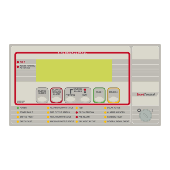
MAN2990-2 Controls and Indicators All controls, except for the Enable / Disable keyswitch, are of a momentary push button style. Figure 14: SmartTerminal Front Panel Layout Note: Keys, when pressed, will present an audible feedback “beep” to the user. KEYSWITCH Access levels There are two levels of access. - Page 15 MAN2990-2 The Following are all accessible at access level 2 and above SILENCE BUZZER Silence Buzzer – Silences the panel buzzer. Buzzer is activated under the following conditions: Alarm Buzzer - ➢ Fire condition Fault Buzzer - ➢ Fault with loop devices ➢...
- Page 16 MAN2990-2 DISABLE Disable – Context sensitive toggle function to disable/enable point displayed on active status screen Illuminated when one or more devices are reporting the FIRE condition or the evacuate control has been activated. Illuminated when the designated FARE input is active. The indication shall remain until the fire alarm condition is reset Illuminated to show the presence of mains power and flashes when the mains have failed...
- Page 17 MAN2990-2 Indicator is illuminated steady when one or more zones are configured with Investigation delays and Delay Mode is active. The indicator shall flash if any Investigation delay timer is running. If the override control or evacuate control is activated while the investigation delay timer is running, then the indicator shall go steady and the investigation zone shall enter the fire condition.
-
Page 18: Lcd Screen Format
MAN2990-2 LCD Screen Format There are 3 events that can be reported and displayed by SmartTerminal. The types of event are; ➢ Fire ➢ Faults and ➢ Disables. The types of events are only associated with sensors and detectors hence faults associated with modules, loops O/C –... - Page 19 MAN2990-2 Pre-alarm: If configured the screen format for reporting loop / sensor / zone Pre-alarm condition is: Zzzz PRE-ALARM <zone descriptor> <date> <time> CONTROL* ZONE DISABLED XXX OF XXX DEVICE► Normal / Default: The format for reporting that everything is normal is: <DATE>...
-
Page 20: Specifications
MAN2990-2 10 Specifications MECHANICAL Dimensions ABS Cabinet BX05: (mm) 195mm (H) x 345mm (W) x 50mm (D) Dimensions ABS Cabinet BX1: (mm) 300mm (H) x 360mm (W) x 100mm (D) ENVIROMENTAL Temperature: -5ºC to + 55ºC Humidity: 25% to 75% non condensing INPUT POWER Operating Voltage (nominal): 27VDC... -
Page 21: Trouble Shooting Chart
MAN2990-2 11 Trouble Shooting Chart Problem Solution Normal Supply LED not illuminated Check supply voltage it should be set to 27.2VDC. Nominal fault voltages are - Low = (<18VDC) High = (> 28VDC ) FACP Earth Fault LED illuminated Check all input and output cabling and wiring assemblies for short to ground FACP System Fault LED illuminated Ensure correct panel configuration... - Page 22 UNCONTROLLED DOCUMENT NOTE: Due to AMPAC’s commitment to continuous improvement specifications may change without notice.
Need help?
Do you have a question about the Ampac SmartTerminal AS7240 and is the answer not in the manual?
Questions and answers