
Related Manuals for Halma ZoneSense Plus AS


Summary of Contents for Halma ZoneSense Plus AS
- Page 1 Fire detection and evacuation solutions that save lives. ZoneSense Plus AS Installation & Commissioning of Control & Monitoring Add-Ons MAN1565-4...
-
Page 2: Table Of Contents
MAN1565-4 Contents About This Manual ..........................3 Introduction ..........................3 General Requirements ........................3 References ........................... 3 Symbols ............................3 System Overview ..........................4 ZoneSense PLUS Description ....................... 5 Placing the Basic System into Operation ..................... 6 PCB Removal / Replacement......................6 Main Control Board .......................... -
Page 3: About This Manual
MAN1565-4 1 About This Manual 1.1 Introduction This manual contains all the information required to install, commission and operation of ancillary module and boards that can be fitted to the standard ZoneSense PLUS and ZoneSense PLUS - AR Fire Alarm Control Panel (FACP) and is only available to and for the use of personnel engaged in its installation, commissioning and operation. -
Page 4: System Overview
MAN1565-4 2 System Overview The ZoneSense PLUS 4 and 8 zone FACP complies with the highest level of approval for any applicable code and can be connected to an appropriate Fire Service monitoring facility. As a Minimum, the conventional panel meets the following Standards; ➢... -
Page 5: Zonesense Plus Description
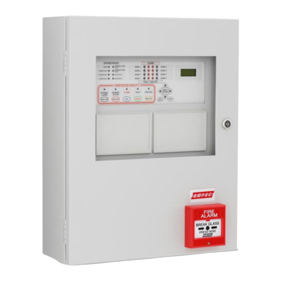
MAN1565-4 3 ZoneSense PLUS Description The ZoneSense PLUS Fire Alarm Control Panel (FACP) is approved to AS4428 and is available in ABS (BX1) or metal cabinets (BX20) with either four (4) or eight (8) zone conventional detection circuits. The 2 line LCD display allows the user to view system status, faults/isolates, prompts for system commands; and guides the user during on-site programming. -
Page 6: Placing The Basic System Into Operation
MAN1565-4 4 Placing the Basic System into Operation 4.1 PCB Removal / Replacement If the PCB’s have to be removed the following precautions should be observed; ➢ Removing the door will provide better access to the boards and ensure the hinges are not accidentally stressed. -
Page 7: Main Control Board
MAN1565-4 5 Main Control Board The Main Control Card and its front display panel combined with the Power Supply / Battery Charger and batteries form the basis for the ZoneSense PLUS FACP. ASSEMBLED BRIDGE SHIELD BRIDGE DECAL Figure 2: Exploded view of the Control Panel M O N RELAY MON O/Ps 1 - 4... -
Page 8: Connector Numbering
MAN1565-4 5.1 Connector numbering Connector Purpose /Pins Link pins & when the front panel keyswitch is NOT used. LCD Driver CN3 & 4 LCD Back Lighting Comms and +/- 27V and earth to the backpan boards. (Imax = 400mA) Pins &... -
Page 9: Terminal Block Numbering
MAN1565-4 5.2 Terminal Block Numbering Terminal Block TP Number AS4428 COMMUNICATIONS EXTERNAL TB2/1 RS485 + RS485 - Shield INPUTS TB3/1 Common Door Switch (monitored) Manual Call Point (monitored) Fault Input (monitored) ZONES ( 25mA / Zone ) TB13/1 + Zone 1 - Zone 1 + Zone 2 - Zone 2... - Page 10 MAN1565-4 Ohms Warn Sys Bell Ohms Note: If a diode is NOT fitted internally to the Bell / Sounder a diode MUST be fitted as shown - fit 1N4004 or similar Figure 5: General Wiring Diagram ZoneSense PLUS...
-
Page 11: Earth Monitoring
MAN1565-4 5.3 Earth Monitoring The earth monitoring disable/enable feature is accessible via the SYSTEM menu at access level 3. Disabling the earth monitoring does not illuminate the Earth Fault LED on the control panel. Note: If ZoneSense PLUS is connected to a third party system which has earth monitoring and it’s earth monitoring is being affected by ZoneSense PLUS even after being disabled through programming the resistor R22 on the Main Card in ZoneSense PLUS can be removed. -
Page 12: Expanding The Facp With Compatible Ancilliary Board
MAN1565-4 6 Expanding the FACP with compatible Ancilliary Board The addition of or a combination of the modules / boards / cards listed below and mounted on the back pan or the front panel of the FACP provide additional control and monitoring facilities to a standard panel. All board inputs or outputs are programmable to any combination of zones. -
Page 13: Installation And Wiring Of Add On Cards And Boards
MAN1565-4 6.3 Installation and Wiring of Add On Cards and Boards Figure 7: Add On Card and Board Positioning Within the ABS FACP... -
Page 14: Links, And Settings
MAN1565-4 6.4 Links, and Settings Except for the Zone Mimic Indicator Card in ZoneSense PLUS FACP’s there can only be one (1) board / Card of each type so the address on each board is set to 1. Note: There can be up to 8 remote Zone Mimic Indicator Cards so the address of each is set from 1 to 8 depending on the actual number of LED Mimics in the system. -
Page 15: Way Switch And Indicator Card
MAN1565-4 6.5 8 Way Switch and Indicator Card This card has 8 switch inputs and 8 LED indicator outputs. The switch inputs and LED outputs may be used in Cause and Effects. The switches are configurable as either momentary or toggle switches. When configured as momentary pressing the button once will cause an event to occur as programmed in C&E and the LED’s can be programmed to operate as an output C&E effect. -
Page 16: Way Input Board
MAN1565-4 6.6 16 Way Input Board The Input Board makes provision for 16 voltage free contacts to be terminated to 16 optically coupled inputs. Its application is primarily for the monitoring of controlled ancillary equipment or to initiate an action / event due to a change of state from what is accepted as the norm. -
Page 17: 8-Way Relay Board
MAN1565-4 6.7 8-Way Relay Board The Relay Board provides 8 programmable relays with 30VDC 1 Amp voltage free change over contacts for control or monitoring purposes and comes fitted for internal or external FACP use. The functionality and programming of the relays is similar to the relays on the main board of the FACP. By default the relays default to Common Alarm functionality. -
Page 18: Remote Relay Board
MAN1565-4 6.7.2 Remote Relay Board In the remote version the Comms In and Out Terminal Block TB9 is cabled to the RS485 Comms terminal block TB1/1, 2, 3 on the Main Board and can be installed up to 1.2kms from the FACP. ... -
Page 19: 8-Way Sounder Board
MAN1565-4 6.8 8-Way Sounder Board The Sounder Board expands the number of sounders that can be used on an FACP by 8. Each output is of a solid state design, rated at 24VDC / 750mA and requires a 10KΩ End of Line (EOL) resistor regardless of whether or not a sounder is wired to the circuit. -
Page 20: Way Fire Fan Module
MAN1565-4 6.9 4 Way Fire Fan Module The Fire Fan Module has four (4) separate fan controls each having an On, Auto and Off function switch and a set of three (3) monitoring LED’s. The LED’s indicate the status of the equipment e.g. Run, Fault or Stop. The two (2) arrow head keys are used to step up and / or down through the three (3) conditions. -
Page 21: Way Fan Termination Board
MAN1565-4 6.10 4 Way Fan Termination Board The Fan Termination Board interfaces between the Fire Fan Module and the plant/equipment it controls via the 24 volt 250mA Start, Stop, current limited, relay outputs and monitor inputs. Programmable monitoring of the field equipment is achieved using 0 volts as an input level to indicate run, fault and stop conditions of that equipment. - Page 22 MAN1565-4 N/0 = Normally Open COM N/C COM N/C COM N/C COM N/C COM N/C COM = Common ALARM 1 FAULT ISOLATE BATT FAIL ALARM 2 N/C = Normally Closed Wired To the Appropriate Relay or Interface Address SW SET to 1 RS485 Control /27VDC 1 2 3 4 Fit EOL Termination...
-
Page 23: Brigade Connections
MAN1565-4 6.11.1 Brigade Connections The ASE Brigade Box interfaces the Victorian Fire Brigade into the LoopSense series of FACP’s. TB10 NOTE: THE BATT FAIL RELAY FAULT ISOL ON THE BRIGADE BOARD ALARM BATT FAIL IS NORMALLY ENERGISED BRIGADE DURING NORMAL C O M OPERATION OF THE SYSTEM MONITOR... -
Page 24: General Indicator Card
MAN1565-4 6.12 General Indicator Card IMPORTANT Note: The Cards BRD25GIB – A, B, C, D and E all have a common PCB. What sets them apart from each other is not only the function they perform but how the componentry is loaded onto the card to perform that function. This Card indicates / displays the status of the inputs on the 16 Way Input Termination Board by way of Program selectable tri-coloured LED’s The function is identified on the front panel by slip in labels whose lettering must no smaller than 3 mm. -
Page 25: Led Annunciator Master (Lam)
MAN1565-4 6.13 LED Annunciator Master (LAM) The LAM provides remote stand alone FACP status, Alarm and Fault / Isolate Indication of 8 zones. Two push buttons, Lamp Test and Silence Buzzer, provide for local testing of the indicators and buzzer while the buzzer duplicates that at the FACP. - Page 26 MAN1565-4 Silences the buzzer if activated by an alarm or fault condition that has been recognised and announced at the FACP. The LAM buzzer can also be silenced by the FACP silence buzzer function. Indicators There are twenty four active indicators on the front panel of the LAM. Flashing indicators are used, the on / off periods are not less than 0.25 seconds and the flash frequencies are not less than: 1Hz for alarm indications (0.5 second on, 0.5 second off)
-
Page 27: Agent Release Control
MAN1565-4 – Zone Indicators There are two indicators for each of the eight zones. Zone Alarm– Red (x8) Each indicator will show if the individual zone it represents is in the alarm condition (flashing at the alarm rate and then steady when the acknowledge control has been operated at the FACP). Zone Indicators Fault /Isolated–... - Page 28 MAN1565-4 ➢ Stage 2 outputs are switched to +24VDC. (FIRE ALARM, EVACUATE & DO NOT ENTER signs illuminated, aural alarm sounds). ➢ The optional pre-release start delay is activated (Selected via FACP on-site programming); time out and an ON Interlock signal will then operate the selected release circuitry. ➢...
- Page 29 MAN1565-4 ➢ Electrically isolates the activation circuitry from the agent release device. ➢ Operates the System Inoperative output. Note: The service switch is NOT overridden by a manual discharge. Lock-Off Valve When the manual lock-off valve is operated; ➢ The agent is blocked from reaching the release valve. ➢...
- Page 30 MAN1565-4 ➢ Operation of the Service Switch. ➢ A Fault in the selected trigger circuit. ➢ Operation of the Lock-off valve. ➢ Operation of the Inhibit at an Local Control Station. ➢ A Fault in any of the activation zones. ➢...
-
Page 31: Agent Release Module
MAN1565-4 6.16 Agent Release Module The Agent Release Module controls and monitors all the requirements for agent release and carries the slide in label for identification of the agent and application area. Top Module & PCB RS485 RS485 Securing Clips &... -
Page 32: Local Control Station (Lcs)
MAN1565-4 6.17 Local Control Station (LCS) The Local Control Station is supplied fitted into an IP40 rated enclosure and has the same indicators and Manual Release switch as the Agent Release Module within the Fire Alarm Control Panel (FACP) but no Agent Select button or Service Inhibit keyswitch. - Page 33 MAN1565-4 LCS Operation & Controls Lifting the cover and pressing the MCP starts the manual agent release sequence. This two action safety feature prevents any accidental operation of the control and should not be disabled. Agent Release / LCS Indicators There are 12 indicators on both the Agent Release Module and Local Control Station.
- Page 34 MAN1565-4 INTERLOCK (Yellow) Illuminated when the interlock input (e.g. from dampers, doors etc) is off during the discharge sequence – meaning the dampers, doors etc are not closed as they should be or a fault exists. The “Interlock” is overridden after 10 seconds and the agent is released ...
-
Page 35: Agent Release Termination Board
MAN1565-4 TERMINATOR LINK JTAG ONLY USED ON THE LAST LCS ON THE COMMS BUS BRD25ARB5- Address Switch S W2 Set to 1 INHIBIT Local Control Station SWITCH MON. DISABLE MANUAL HOLD/ AGENT INHIBIT INTER- RS 485 IN RS 485 OUT MANUAL LOCK RELEASE... -
Page 36: Interface Wiring
MAN1565-4 3. Monitored Inputs: via TB2. (EOL Resistance 22K, Series Resistance 4K7) ➢ Pressure Switch (PSW) agent released ➢ Low Pressure Switch (LPSW) agent storage cylinder pressure has dropped to a pre-determined level; ➢ Interlock, the manual lock-off valve has been operated. 4. -
Page 37: Warning Signs
MAN1565-4 RL2A To Monitoring Interface / Device = MOV Figure 29 Gas Fired Wiring RL1A To Sys System Inoperative Inop Mon +27V Current Limited to1A Figure 30: System Inoperative Wiring As can be seen from above the; Gas Fired Output can be wired to any interfacing or 1A monitoring circuit that requires a closed relay contact to indicate a change of state. - Page 38 MAN1565-4 Operational Voltage 27VDC At 24VDC 55mA Stage 1 Power Consumption Continuous At 24VDC 140mA Stage 2 (100mA Muted) IP50 190mm (H) x 315mm (W) x 73mm (D) IP Ratings IP65 200mm (H) x 295mm (W) x 65mm (D) -10˚C to +55˚C Dry heat Environmental +40˚C @ 0 to 93% Relative Humidity Installation...
- Page 39 MAN1565-4 Configuration – Jumper Settings JP 1 (Continuous / Flashing) JP 2 (Single / Dual Stage) LED's Permanently Full sign on for Stage 1-2 Continuous 1-2 Single Stage 1&2 Flashing LED's flashing Dual Stage Half sign on for Stage 1 (DEFAULT) 1.5Hz (DEFAULT)
-
Page 40: Occupant Warning Systems
MAN1565-4 6. (+) POS TO NEXT WARNING SIGN IF 5. (+) POS MULTIPLE SIGNS ARE USED C OM+ FIT 10K EOL TO LAST 4. (-) ALERT SIGN ON CHAIN STG1 3. (-) ALERT STG2 2. (-) EVAC B R D 42W TB 2- A 1. - Page 41 MAN1565-4 Short or open circuit speaker faults are detected by the fault monitoring circuitry and will result in the illumination of the FAULT indicator mounted on the front panel control module and “SPEAKER SHORT” (red) or “SPEAKER OPEN” (yellow) LEDs on the main board. Public Address A microphone (Order Code 294-0001) is used to provide the public address capabilities.
- Page 42 MAN1565-4 Control Module When the control switch is in; AUTOMATIC - occupant warning signals and if applicable verbal messaging is under the control of the microprocessor and outputted to the speaker system when it receives a “warning system” signal from the FACP. ISOLATE –...
- Page 43 MAN1565-4 1200Hz "EMERGENCY EVACUATE NOW" 500Hz secs Time in seconds Figure 34: Alert & Evacuation Signal Structures...
- Page 44 MAN1565-4 EV20 Cabling Note: “WARNING SYSTEM” is a monitored O/P. The EOL is on board the EV20 and is effectively made to be O/C (at TB1) during an EV20 fault condition. This produces the fault condition at the FACP. FRONT PANEL Shield Signal...
- Page 45 MAN1565-4 EV40 Cabling 8 OHM SPARE o o o o o JUMPERS o o o o o EVACTRON 40W LINE EV40 TRANSFORMER AMP2 IF NO SPEAKER MONITORING IS REQUIRED 100V IN PLACE A 22K RESISTOR ACROSS TB4 R ED 100V IN TERMINALS 1 &...
- Page 46 MAN1565-4 EV60 The EV60 isessentially an EV20 MPU and driver but with 60 watt output amplifiers powered from a Current Limit Fuse Board. Figure 37: EV60 EV120...
- Page 47 MAN1565-4 FRONT CONTROL CARD Shield Signal (Red) Shield MIC I/P OPTIONAL PUBLIC CONTROL CARD ADDRESS PRE-AMP LINE FAULT ISOLATE TO 100V O/P ON THE TERMINATION BRD AUDIO BRD42ETG PANEL (Power) TERMINAL No TONE VOICE FireFinder Brigade BRD TB2/1 TB2/2 +27V ZoneSense Plus CN10/1 CN10/2 BLACK...
- Page 48 MAN1565-4 EV3000 Relay Board Operation One of the relays on the 8 Way Relay Board will be programmed to operate on “Alarm”. The subsequent shorting of the 10KΩ EOL initiates the Alert / Evac sequence 10K EOL EV3000 INPUT INPUT INPUT INPUT INPUT...
-
Page 49: Certification Information
MAN1565-4 7 Certification Information The ZoneSense PLUS is designed and manufactured by: AMPAC TECHNOLOGIES PTY LTD 7 Ledgar Rd Balcatta WA 6021 HEAD OFFICE Western Australia 61-8-9201 6100 FAX: 61-8-9201 6101 Manufactured to: Certificate of Compliance Number: Equipment Serial Number: Date of Manufacture:... -
Page 50: Specifications
MAN1565-4 8 Specifications Mechanical Dimensions Metal Cabinet: (mm) 500H x 405W x 145D Note: A battery box is available should either model be optioned to capacity. Environmental Temperature: -5ºC to + 55ºC Humidity: 25% to 75% Non condensing Power Supply Input Voltage: 180 - 264VAC ( 47-63Hz ) Protection (Quick Acting Fuse):... -
Page 51: Glossary Of Terms
MAN1565-4 9 Glossary of Terms ACF: ANCILLARY CONTROL FACILITY ACKD: ACKNOWLEDGED AHU: AIR HANDLING UNIT ALM: ALARM AVF: ALARM VERIFICATION FACILITY AZF: ALARM ZONE FACILITY AZC: ALARM ZONE CIRCUIT RELAY COMMON CONTACT (WIPER) CIC: CONTROLLER INTERFACE CARD CONNECTOR CPU: COMMON PROCESSOR UNIT DGP: DATA GATHERING POINT EARTH: BUILDING EARTH... -
Page 52: Definitions
MAN1565-4 10 Definitions Addressable system - a fire alarm and detection system that contains addressable alarm zone facilities or addressable control devices. Alarm Verification Facility (AVF) - that part of the FACP, which provides an automatic resetting function for spurious alarm signals so that they will not inadvertently initiate Master Alarm Facility (MAF), or ACF functions. - Page 53 MAN1565-4 Power Supply - that portion of the FACP which supplies all voltages necessary for its operation. Regulatory Authority - an authority administering Acts of Parliament or Regulations under such Acts.
-
Page 54: Quick Reference Guides
MAN1565-4 11 Quick Reference Guides FAULTS STATUS MENU MENU ENTER ENTER FAULTS F 2 / 2 MENU F 1 / 2 SOFTWARE MENU OUTPUTS VOLTAGE 2 Flt/s ENTER FIRE CTRL ENTER FIRE FAN VER E1.2 MENU MENU CANCEL ENTER ENTER MENU MENU ENTER... - Page 55 MAN1565-4 ENTER MENU SYSTEM ENTER PASSWORD FACTORY DEFAULT MENU PASSWORD IS 3333 ENTER MENU ALARM RESOUND EXAMPLE OF BUZZER ENTER YES / NO YES / NO ENTERING PASSWORD 3333 EXAMPLE MENU ENTER SET RESOUND TO YES THEN MOVE TO ALARM EARTH MON PASSWORD Y E S...
- Page 56 MAN1565-4 Agent Notes: If only one trigger zone is allocated a zone then the system will be activated by one zone only. Any trigger zone may be allocated to any zone. However when a trigger zone has been allocated eg T1 to zone 1 then only the remaining trigger zones T2, T3 or T4 are each available to be PROGRAM allocated one of the remaining detector zones.
-
Page 57: Front Panel Configuration Labelling
MAN1565-4 12 Front Panel Configuration Labelling WARN SOUNDER SOUNDER SOUNDER SOUNDER SOUNDER SOUNDER SOUNDER SOUNDER ZONE CONFIGURATION BELL ALARM B ALARM 1 B ALARM 2 RELAY 1 RELAY 2 RELAY 3 RELAY 4 RELAY 5 RELAY 6 RELAY 7 RELAY 8 FAN 1 FAN 2 FAN 3... - Page 58 MAN1565-4 UNCONTROLLED DOCUMENT NOTE: Due to AMPAC’s commitment to continuous improvement specifications may change without notice.