
Related Manuals for Halma Ampac ZoneSense Plus


Summary of Contents for Halma Ampac ZoneSense Plus
- Page 1 Fire detection and evacuation solutions that save lives. ZoneSense Plus Operation & Programming MAN1544-5...
- Page 2 MAN1544-5 Isolating a Zone 1. Indicator - Zone Alarm Indicator (flashing) - Common Alarm Indicator (flashing) - First Zone in Alarm is displayed on the LCD. Z7 ZONE SEVEN 2. To Isolate External Bell press 3. To Isolate Warning System press 4.
- Page 3 MAN1544-5 Isolating a Zone Example below isolates Zone 2) AMPAC SU 00 : 15 Default Screen Moving to the ISOLATE MENU FAULTS STATUS Press press ISOLATES TEST Press press ZONE 1 ZONES ACTIVE ISOL'D Press press ...
-
Page 4: Table Of Contents
MAN1544-5 Contents About This Manual ..........................6 Introduction ..........................6 General Requirements ........................6 References ........................... 6 Symbols ............................6 Controls & Indicators – Front Panel ..................... 7 System Controls & Indicators ......................7 Level of Access ..........................7 FireFighter Facility Controls and Indicators ................... 8 System Controls.......................... - Page 5 MAN1544-5 5.3.4 Outputs ..........................28 5.3.5 Relays ..........................29 5.3.6 Fire Fan ..........................30 5.3.7 Agent ...........................32 5.3.8 Sounders ..........................33 5.3.9 Indicate ..........................33 5.3.10 Display ..........................34 5.3.11 Zone Labels ..........................34 5.3.12 End Of Line (EOL) .........................34 5.3.13 Zone S/C ..........................34 Agent Release .............................35 Controls............................35 LocalControl Station ........................36 Common Agent Release Card &...
-
Page 6: About This Manual
MAN1544-5 1 About This Manual 1.1 Introduction This manual contains all the information required to install, and operate the ZoneSense PLUS - AR Fire Alarm Control Panel (FACP) and is only available to and for the use of personnel engaged in its installation, commissioning and operation. -
Page 7: Controls & Indicators - Front Panel
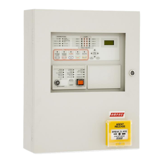
MAN1544-5 2 Controls & Indicators – Front Panel 2.1 System Controls & Indicators The front panel controls for the ZoneSense PLUS - AR consists of twelve push buttons and an optional Normal / Enabled key switch. Figure 1: AS4428 8 Zone Front Panel Controls and Indicators 2.2 Level of Access Access to the FACP is restricted to three levels of authorisation. -
Page 8: Firefighter Facility Controls And Indicators
MAN1544-5 2.3 FireFighter Facility Controls and Indicators Note: Any of the buttons within the FireFighter Facility will act as a buzzer mute. External Alarm Isolate Is a dedicated control used to isolate (turn off) the “External Alarms” output and is not over ridden by any other condition. The LCD Screen will display the isolate if the ISOLATES / OUTPUTS menu is selected. -
Page 9: System Controls
MAN1544-5 2.4 System Controls Enter or Menu is used to access the various menus and sub-menus and update the program once the control settings have been set within a menu. Move Left allows the operator to move left through a menu or the options to be set. Move Right allows the operator to move right through a menu or the options to be set Move Up takes the cursor up through the menus and / or options. -
Page 10: Indicators - Front Panel
MAN1544-5 2.6 Indicators – Front Panel All indicators are clearly visible at all times. If flashing indicators are used the on / off periods are >0.25 seconds and the flash frequencies are not less than: ➢ 1Hz for Alarm indications. ➢... -
Page 11: Zone Indicators
MAN1544-5 2.6.2 Zone Indicators There are two indicators for each alarm zone fitted to the panel. Zone Alarm – Red The indicators show individual zone/s in alarm. On alarm the LED will flash until the alarm is acknowledged. Once acknowledged the LED will be continuously illuminated until the panel is reset. -
Page 12: Main Menu
MAN1544-5 2.8 Main Menu The Main Menu consists of; Level 1 Level 2 Activate Control Level 3 Enter Password STATUS FAULTS TEST DISABLES SYSTEM PROGRAM Press the Move Right / Move Left key to move through the menu. Press to access the sub – menus. Move Right to access STATUS... -
Page 13: Level 1 Access
MAN1544-5 3 Level 1 Access Is a read only menu that allows the operator to reset latched Ancillary Control Facility outputs (IF FITTED); In the event an ancillary device trips out or is operated for some reason the latching control of the device has to be reset to re-establish normal functionality of that device. -
Page 14: Outputs
MAN1544-5 3.1.1 Outputs Press then Move Right or Move Left to view the status of the monitored Bell, Warning System, ACF, ASE, Alarm or Fault Outputs on the Main Control Board. The LCD readout will indicate if the selected Output is: On and Normal, or Off and Normal, or Off and Isolated, or On and Isolated, or Output is On and in Fault, or Off and in Fault. -
Page 15: Relays
MAN1544-5 3.1.3 Relays Press Enter then Move Left or Move Right to select the required Relay (1 – 8). The LCD read out for each relay on the Relay Board will indicate if the selected relay is On, Off or Isolated OR Press Move right to access Fire Fan. -
Page 16: Inputs
MAN1544-5 3.1.7 Inputs Press then Move Right or Move Left to view the status of each input (1 to 16) on the Input Board. INPUT 1 OFF / NOR Figure 8: Sample Input Screens 3.1.8 Voltage Press Move right to access Software OR press and the Battery Voltage will be displayed, pressing Move Right will display the Charger Voltage (approx 27.2volts ), pressing... -
Page 17: Faults
MAN1544-5 3.2 FAULTS Pressing will display all faults in a sequential order. If there is more than one fault on the system the operator can scroll through each fault by using the Move Left and Right keys. Pressing again at each Fault will display more detailed information. Accessing information on 2 Faults FAULTS F 1 / 2... -
Page 18: Level 2 Access
MAN1544-5 4 Level 2 Access At this level the operator is expected to have under gone training so as to be able to; ➢ Test crucial elements of the system and; TEST ➢ Isolate dedicated facilities that may be in fault. ISOLATE In the Main Menu From FAULTS Move Right for TEST... -
Page 19: Fault Test
MAN1544-5 4.1.2 Fault Test Once the test is commenced the Buzzer will rapidly turn on and off and the common Fault and Zone Fault LED’s will flash. Press , the Buzzer will be silenced and the common Fault and Zone Fault LED’s will continue to flash. -
Page 20: Lamp Test
MAN1544-5 4.1.4 Lamp Test Press the Move Right and / or Move Left key to move to the Lamp Test menu, press each LED on the panel will be sequentially turned on for one second and then off again. The Buzzer will sound at the start and completion of the test. -
Page 21: Isolates
MAN1544-5 4.2 Isolates To display the number of Isolates press to access the menus then Move Left or Move Right to select the required menu. The number of isolates will be displayed for each step. Zone [ Main Brd ] Monitored Outputs Relay [ Relay Brd ] Sounder [ Sndr Brd ]... -
Page 22: Main Control Board Outputs Isolates
MAN1544-5 4.2.2 Main Control Board Outputs Isolates Press Enter to access the Isolate – Main Control Board Monitored Outputs sub-menus as seen below Bell Warn Sys Alarm Fault Use the Move Right or Move Left keys to select the required menu and the Move Up key to Isolate or the Move Down key to active. -
Page 23: Level 3 Access Programming
MAN1544-5 5 Level 3 Access Programming Level 3 is a technical level that allows a technician to; SYSTEM , Initialise the FACP so it is capable of recognising how the system is constructed; and PROGRAM program how it will present information as well as how it will react to a change of state of an input and / or output 5.1 Password Entry Returning to Faults in the Main Menu, Move Right for Password Entry to Level 3. -
Page 24: System
MAN1544-5 5.2 System After entering the Level 3 Password and moving to the SYSTEM menu press and the; Zone ISOLATE LED’s will illuminate; Common ISOLATED LED will flash; and the LCD will display; BUZZER SYSTEM DISABLED SYSTEM DISABLED And then BUZZER Ignoring Buzzer, Mimic and Code menus ( explained below ) use the Move Right or... -
Page 25: Led Annunciator Master ( Lam )
MAN1544-5 5.2.2 LED Annunciator Master ( LAM ) This tells the FACP how many LAM’s are on the system hence how many to look for. Set the number by using the Move Down and / or Move Up keys to increment to the desired number 0 to 8 (maximum of 8). -
Page 26: Program
MAN1544-5 5.3 Program Note: From the Zones Menu use the Move Right key to advance through the PROGRAM Menu. Pressing Enter to access the Program Menu will again disable the panel and the LED’s will illuminate as they did in the Systems Menu. The PROGRAM Menu consists of;... -
Page 27: Clock
MAN1544-5 Any trigger zone may be allocated to any zone. However when a trigger zone has been allocated eg T1 to zone 1 then only the remaining trigger zones T2, T3 or T4 are each available to be allocated one of the remaining detector zones. -
Page 28: Outputs
MAN1544-5 5.3.4 Outputs To assign Zones that will activate the monitored outputs press and a sub menu will be made available for programming. The default condition for each output is all Zones will activate all outputs. The sub menu consists off; Outputs Bell Warn Sys... -
Page 29: Relays
MAN1544-5 5.3.5 Relays Press then use the Move Right and / or Move Left keys to select a relay that will be operated by the selected functions in the sub - menu . Press to access the sub – menu then Move Right and /or Move Left keys to toggle through the sub - menu structure. -
Page 30: Fire Fan
MAN1544-5 5.3.6 Fire Fan FAN 2 The sub menu consists of; Alarm Inhibit Function Latch ACF Isolate For: Alarm Inhibit Press then use the Move Right and / or Move Left keys to select the Fire Fan that will be controlled by the selected functions in the sub - menu . - Page 31 MAN1544-5 Press and the cursor will flash over YES or NO and then the Move Up key for Yes to set the card to be latching or Move Down key for No to set the card for non-latching on alarm. LATCHING LATCHING Press...
-
Page 32: Agent
MAN1544-5 5.3.7 Agent If Yes was selected in the SYSTEM menu the Sub – Menu seen below will be available. Press Enter to access the sub-menu. The sub-menu consists off; Release Press Sw Auto Delay Man Delay No LCP’s LCS Buzzer NO/NC/None Normal Solenoid... -
Page 33: Sounders
MAN1544-5 5.3.8 Sounders Press then use the Move Right and Move Left keys to select a sounder. Press again and use the Move Right and Move Left keys to select a Sounder, Press again and the Move Up and Move down keys to set that Sounder to a Zone to activate or not activate the selected sounder. -
Page 34: Display
MAN1544-5 5.3.10 Display To set the message, FACP or company name press and use the Move Right and Move Left keys to move through the word to select a letter and the Move Up and the Move Down keys to move through the alphabet. A maximum of 16 characters are available for this message. AMPAC <... -
Page 35: Agent Release
MAN1544-5 6 Agent Release Top Module & PCB TERMINATOR LINK Securing Clips ADDRESS Fit EOL Termination SWITCH S W2 Link 1 if Last Module on Comms Bus INHIBIT RS485 Control RS485 Control SWITCH MON DISABLE / 27VDC / 27VDC Comms In Comms Out MANUAL RELEASE... -
Page 36: Localcontrol Station
MAN1544-5 6.2 LocalControl Station The Local Control Station is supplied fitted into an IP40 rated enclosure and has the same indicators and Manual Release switch as the Agent Release Module within the Fire Alarm Control Panel (FACP) but no Agent Select button or Service Inhibit keyswitch. The Comms line is RS485 and is cabled to the Agent Termination Board. -
Page 37: Common Agent Release Card & Lcs Indicators
MAN1544-5 LCS Operation & Controls Lifting the cover and pressing the MCP starts the manual agent release sequence. This two action safety feature prevents any accidental operation of the control and should not be disabled. 6.3 Common Agent Release Card & LCS Indicators There are 12 indicators on both the Agent Release Module and Local Control Station. - Page 38 MAN1544-5 LCS fault (missing or extra), trigger zone(s) fault, low agent pressure and interlock fault. INTERLOCK (Yellow) Illuminated when the interlock input (e.g. from dampers, doors etc) is off during the discharge sequence – meaning the dampers, doors etc are not closed as they should be or a fault exists.
-
Page 39: Agent Release Operation
MAN1544-5 6.4 Agent Release Operation The agent release can release the agent via automatic or manual activation. By default the agent release add-on is in a mode where a release occurs automatically or manually (automatic mode). When the agent inhibit switch is operated at any LCS or the FACP then the agent inhibit indicator shall be illuminated at all LCSs and the ARC, the buzzer sounds at all LCSs and the agent can only be released by a manual activation. -
Page 40: Auto Mode
MAN1544-5 ➢ Light the agent release indicator on the ARC at the FACP and LCSs when the pressure switch input on the termination board is activated or immediately (depends on the pressure switch configuration – refer to FACP on-site programming). ➢... -
Page 41: Dual Zone Activation
MAN1544-5 ➢ If the agent add-on has been assigned a zone number, then the brigade and supervisory outputs associated with that zone shall be activated (external alarm (bell), warning system, plant (ACF), ASE, Alarm 1 and Alarm 2). ➢ When the FACP reset control is activated – the automatic activation indicator, agent discharge indicator, stage 2 timer running are extinguished, and the stage 1, stage 2, selected activation circuit and gas fired output are switched off (to 0VDC). - Page 42 MAN1544-5 ➢ If the agent add-on has been assigned a zone number, then the brigade and supervisory outputs associated with that zone shall be activated (external alarm (bell), warning system, plant (ACF), ASE, Alarm 1 and Alarm 2). If the agent select button is operated at the ARC once the agent has been released, then the newly selected activation circuit is operated immediately.
-
Page 43: Manual Activation
MAN1544-5 6.6.3 Manual Activation It shall be possible to instigate a manual release whilst the module is in the auto mode. A manual release is initiated by operating the manual release control at the ARC or the LCS. If an automatic release sequence has not started, then the manual release sequence proceeds as detailed in previously. -
Page 44: Fault Supervison
MAN1544-5 6.9 Fault Supervison ➢ The sources of fault in the system are: ➢ Pressure switch ➢ Low pressure switch ➢ Lock-off valve ➢ Selected activation circuit ➢ Stage 1 outputs ➢ Stage 2 outputs ➢ Fault in the trigger zones ➢... -
Page 45: Manual Mechanical Release Of The Agent
MAN1544-5 6.12 Manual Mechanical Release of the Agent With agent release systems, a manual mechanical means can be provided to release the agent. If the pressure switch is activated (indicating that the agent has been released),and the agent release add- on has not activated the selected activation circuit, then the following will occur: ➢... -
Page 46: Warning Device
MAN1544-5 7 Warning Device Description The warning signs are driven by a 2 wire system and may be configured for single or dual stage operation. An on-board buzzer provides an audible warning which may be disabled by removing JP4. External evacuation devices, e.g. sounders may be connected to TB4 of the input termination board. An external mute push-button (N/O contacts) may also be connected to Term 6 on the warning sign PCB to enable the user to silence the internal buzzer and evacuation device. - Page 47 MAN1544-5 Configuration – Jumper Settings Jumper No. Description JP-1 1 – 2 Dual Level Top row LED’s will be ON at Level 1 Alarm All LED’s will be ON at Level 2 Alarm 2 - 3 Single Level All LED’s will be ON at both Level 1 and 2 Alarm JUMPER NUMBERING LED’s permanently ON...
- Page 48 MAN1544-5 6. (+) POS WARN SYS (ALM OUT) 5. (+) POS e.g. FireFinder Plus 4. (-) ALERT 3. (-) ALERT WARN SYS 2. (-) EVAC (ALM OUT) e.g. LoopSense 1. (-) EVAC WARN SYS VANTAGE SOUNDER (ALM OUT) NOT REQUIRED FOR SINGLE e.g.
-
Page 49: Appendix A: As4428 Menu Structure & Programming
MAN1544-5 8 Appendix A: AS4428 Menu Structure & Programming STATUS FAULTS TESTS ISOLATE SYSTEM PROGRAM Status PRESS ENTER TO GO TO SUB MENU, PRESS THESE KEYS PRESS CANCEL AT CANCEL MENU SET MENU OR UPDATE PROGRAM TO SET YES / NO, OFF / ON, ANY TIME TO BACK STATUS ENTER... - Page 50 MAN1544-5 Faults PRESS CANCEL AT ANY TIME TO BACK MENU CANCEL LEGEND: PRESS ENTER TO GO TO MENU OUT OF THE MENU OR STOP TEST FAULTS ENTER MENU ENTER PRESS TO VIEW DETAILS OF EACH FAULT MENU CANCEL ENTER FAULTS F 1 / 2 F 2 / 2 MENU...
- Page 51 MAN1544-5 Test PRESS CANCEL AT ANY TIME TO BACK MENU CANCEL LEGEND: PRESS ENTER TO START TEST OUT OF THE MENU OR STOP TEST ENTER TEST MENU ENTER PRESS TO INCREMENT UP DOWN ZONE NUMBER TO BE TESTED MENU CANCEL ENTER ZONE 2 ZONE 6...
- Page 52 MAN1544-5 System (Password required) ENT ER MENU ALARM MENU RESOUND MENU SYSTEM BUZZER ENTER PASSWORD ENTER ENTER YES / NO YES / NO FACTORY DEFAULT EXAMPLE PASSWORD IS 3333 SET RESOUND TO YES THEN MOVE TO ALARM EXAMPLE OF Y E S EARTH MON ENTERING YES / NO...
- Page 53 MAN1544-5 Program Agent Notes: If only one trigger zone is allocated a zone then the system will be activated by one zone only. Any trigger zone may be allocated to any zone. However when a trigger zone has been allocated eg T1 to zone 1 then only the remaining trigger zones T2, T3 or T4 are each available to be PROGRAM allocated one of the remaining detector zones.
-
Page 54: Trouble Shooting Chart
MAN1544-5 9 Trouble Shooting Chart Problem Solution No Mains Power Check mains Fuse Check output voltage it should be set to 27.2VDC. Low = (less than 26.5VDC ) Supply fault LED illuminated High = (greater than 28VDC ) Check the battery has been connected properly Check all input and output cabling and wiring Earth Fault LED illuminated assemblies for short to ground... -
Page 55: Certification Information
MAN1544-5 10 Certification Information The ZoneSense PLUS - AR is designed and manufactured by: AMPAC TECHNOLOGIES PTY LTD 7 Ledgar Rd Balcatta WA 6021 Western Australia 61-8-9201 6100 FAX: 61-8-9201 6101 Manufactured to: Certificate of Compliance Number: Equipment Serial Number: Date of Manufacture:... -
Page 56: Glossary Of Terms
MAN1544-5 11 Glossary of Terms ACF: ANCILLARY CONTROL FACILITY ACKD: ACKNOWLEDGED AHU: AIR HANDLING UNIT ALM: ALARM AVF: ALARM VERIFICATION FACILITY AZF: ALARM ZONE FACILITY AZC: ALARM ZONE CIRCUIT RELAY COMMON CONTACT (WIPER) CIC: CONTROLLER INTERFACE CARD CONNECTOR CPU: COMMON PROCESSOR UNIT DGP: DATA GATHERING POINT EARTH:... -
Page 57: Definitions
MAN1544-5 12 Definitions Addressable system - a fire alarm and detection system that contains addressable alarm zone facilities or addressable control devices. Alarm Verification Facility (AVF) - that part of the FACP, which provides an automatic resetting function for spurious alarm signals so that they will not inadvertently initiate Master Alarm Facility (MAF), or ACF functions. - Page 58 MAN1544-5 Master Alarm Facility (MAF) - that part of the equipment which receives alarm and fault signals from any alarm zone facility and initiates the common signal (alarm and/or fault) for transmission to the fire control station. Bells and other ancillary functions may be initiated from this facility. Power Supply - that portion of the FACP which supplies all voltages necessary for its operation.
- Page 59 MAN1544-5 UNCONTROLLED DOCUMENT NOTE: Due to AMPAC’s commitment to continuous improvement specifications may change without notice.
Need help?
Do you have a question about the Ampac ZoneSense Plus and is the answer not in the manual?
Questions and answers