Table of Contents
Advertisement
Quick Links
Advertisement
Table of Contents

Related Manuals for Deye SUN-5K-SG01HP3-AU-AM2


Summary of Contents for Deye SUN-5K-SG01HP3-AU-AM2
- Page 1 Hybrid Inverter SUN-5K-SG01HP3-AU-AM2 SUN-6K-SG01HP3-AU-AM2 SUN-8K-SG01HP3-AU-AM2 SUN-10K-SG01HP3-AU-AM2 05/28/2019 15:34:40 8.30 -3.00 -2.00 3.00 SUN-12K-SG01HP3-AU-AM2 SUN-15K-SG01HP3-AU-AM2 SUN-20K-SG01HP3-AU-AM2 SUN-25K-SG01HP3-AU-AM2 User Manual...
-
Page 2: Table Of Contents
Contents 1. Safety Introductions ………………………………………………… 2. Product instructions 02-05 ………………………………………………… 2.1 Product Overview 2.2 Product Size 2.3 Product Features 2.4 Basic System Architecture 2.5 Maintenance of the System 2.6 Product handling requirements 3. Installation 05-24 …………………………………………………………… 3.1 Parts list 3.2 Mounting instructions 3.3 Battery connection 3.4 Grid connection and backup load connection 3.5 PV Connection... - Page 3 Documents must be stored carefully and be available at all �mes. Contents may be periodically updated or revised due to product development. The informa�on in this manual is subject to change without no�ce. The latest manual can be acquired via service@deye.com.cn 1. Safety Introduc�ons Safety signs...
-
Page 4: Product Overview
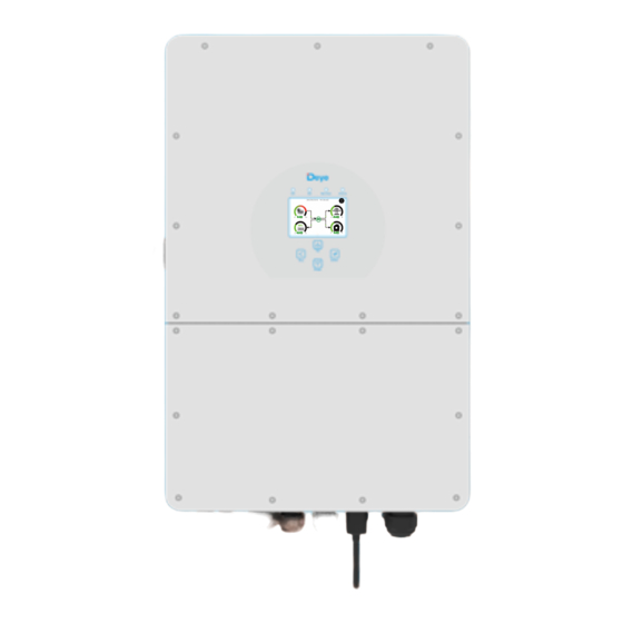
2. Product Introduc�ons This is a mul�func�onal inverter, combining func�ons of inverter, solar charger and ba�ery charger to offer uninterrup�ble power support with portable size. Its comprehensive LCD display offers user configurable and easy accessible bu�on opera�on such as ba�ery charging, AC/solar charging, and acceptable input voltage based on different applica�ons. -
Page 5: Product Size
2.2 Product Size SUN-5/6K-SG01HP3-AU-AM2 SUN-8/10K-SG01HP3-AU-AM2 SUN-12/15K-SG01HP3-AU-AM2 Inverter Size SUN-20/25K-SG01HP3-AU-AM2 - 03 -... -
Page 6: Product Features
2.3 Product Features - 230V/400V Three phase Pure sine wave inverter. - Self-consump�on and feed-in to the grid. - Auto restart while AC is recovering. - Programmable supply priority for ba�ery or grid. - Programmable mul�ple opera�on modes: On grid, off grid and UPS. - Configurable ba�ery charging current/voltage based on applica�ons by LCD se�ng. -
Page 7: Product Handling Requirements
2.5 Product handling requirements Two people stand on both sides of the machine, holding one handles to li� the machine. transport 3. Installa�on 3.1 Parts List Check the equipment before installa�on. Please make sure nothing is damaged in the package. You should have received the items in the following package: Stainless steel an�-collision Parallel communica�on... - Page 8 3.2 Moun�ng instruc�ons Installa�on Precau�on This Hybrid inverter is designed for outdoor use(IP65), Please make sure the installa�on site meets below condi�ons: · Not in direct sunlight · Not in areas where highly flammable materials are stored. · Not in poten�al explosive areas. ·...
- Page 9 ≥500mm ≥500mm For proper air circula�on to dissipate heat, allow a clearance of approx. 50cm to the side and approx. 50cm above and below the unit. And 100cm to the front. Moun�ng the inverter Remember that this inverter is heavy! Please be careful when li�ing out from the package. Choose the recommend drill head(as shown in below pic) to drill 4 holes on the wall, 62-70mm deep.
- Page 10 3.3 Ba�ery connec�on For safe opera�on and compliance, a separate DC over-current protector or disconnect device is required between the ba�ery and the inverter. In some applica�ons, switching devices may not be required but over-current protectors are s�ll required. Refer to the typical amperage in the table below for the required fuse or circuit breaker size.
- Page 11 b) Crimping metal terminals with crimping pliers as shown in picture 3.4. Pic 3.4 Crimp the contact pin to the wire c) Insert the contact pin to the top part of the connector and screw up the cap nut to the top part of the connector.
- Page 12 3.3.2 Func�on port defini�on Inverter Meter Parallel_1 Parallel_2 BMS1 BMS2 RS485 1 2 3 4 5 6 7 8 9 10 1112 1 2 3 4 5 6 7 8 9 10 1112 SHUT DOWN Meter: for energy meter communica�on. Parallel_1: Parallel communica�on port 1.
- Page 13 3.4 Grid connec�on and backup load connec�on · Before connec�ng to the grid, a separate AC breaker must be installed between the inverter and the grid, and also between the backup load and the inverter. This will ensure the inverter can be securely disconnected during maintenance and fully protected from over current.
-
Page 14: Pv Connection
Be sure that AC power source is disconnected before a�emp�ng to wire it to the unit. 3. Then, insert AC output wires according to polari�es indicated on the terminal block and �ghten terminal. Be sure to connect corresponding N wires and PE wires to related terminals as well. 4. - Page 15 Inverter Model 10kW 12kW 15kW 20kW 25kW PV Input Voltage 600V (180V~1000V) PV Array MPPT Voltage Range 150V-850V No. of MPP Trackers No. of Strings per MPP Tracker Chart 3-5 3.5.2 PV Module Wire Connec�on: 1. Switch the Grid Supply Main Switch(AC)OFF. 2.
- Page 16 Safety Hint: Please use approved DC cable for PV system. Cross section(mm ) Cable type Range Recommended value Industry generic PV cable 2.5-6 6(10AWG) (model: PV1-F) (12~10AWG) Chart 3-6 The steps to assemble the DC connectors are listed as follows: a) Strip off...
- Page 17 Please use its own DC power connector from the inverter accessories. Do not interconnect the connectors of different manufacturers.Max. DC input current should be 20A. if exceeds, it may damage the inverter and it is not covered by Deye warranty. - 15 -...
-
Page 18: Ct Connection
3.6 CT Connec�on GRID Inverter 1 2 3 4 5 6 7 8 9 10 1112 Black wire White wire Arrow pointing inverter Grid *Note:when the reading of the load power on the LCD is not correct, please reverse the CT arrow. - 16 -... - Page 19 3.6.1 Meter Connec�on GRID Inverter Meter Parallel_1 Parallel_2 Three-Phase Smart Meter RS485A Grid RS485B Three-Phase Smart Meter (1,4,7,10) (3,6,9,10) RS 485 CHINT meter CHNT DTSU666 GRID Inverter Meter Parallel_1 Parallel_2 RS485B RS485A 1 2 3 4 5 6 7 8 Eastron Grid (1,2,3,4)
- Page 20 GRID Inverter Meter Parallel_1 Parallel_2 AC Breaker RS485A RS485B Home Load AC Breaker Three-Phase Smart Meter Grid Blue line White line Blue line White line Blue line Note: the arrow direc�on towards the inverter White line 6 9 10 13 14 16 17 19 21 (3,6,9,10) Three-Phase Smart Meter...
- Page 21 GRID Inverter Meter Parallel_1 Parallel_2 AC Breaker Home Load AC Breaker NA LA L1 L2 L3 N Grid S1 S2 S1 S2 S1 S2 Black line Red line Black line Red line Black line Note: the arrow direc�on Red line towards the inverter 9 1 0 11 1 2 1 3 1 4 1 5 1 6 1 7 1 8 1 9 2 0 Eastron...
-
Page 22: Earth Connection(Mandatory)
Note: When the inverter is in the off-grid state, the N line needs to be connected to the earth. Note: inverter has built–in leakage current detec�on circuit,If an external RCD is required,a type-A RCD with rated residual current of 300mA or higher is suggested.Otherwise inverter may not work properly. - Page 23 For mobile phone monitoring system, scan the QR code to download the APP. Also you can find it by searching “solarman business” in App store or Google Play store, and this App is for distributor/installer. Find it by searching “solarman smart” in App store or Google Play store and choose “solarman smart”, this app is for plant owner.
-
Page 24: Wiring System For Inverter
3.10 Wiring System for Inverter - 22 -... -
Page 25: Wiring Diagram
3.11 Wiring diagram L wire N wire PE wire BMS1 BMS2 Inverter Ground ①DC Breaker Battery pack ②AC Breaker ③AC Breaker CT1 CT2 Grid ④AC Breaker Home Load ① DC Breaker for battery SUN 5K-SG-AU: 80A DC breaker Backup Load SUN 6K-SG-AU: 80A DC breaker SUN 8K-SG-AU: 80A DC breaker SUN 10K-SG-AU: 80A DC breaker... -
Page 26: Typical Application Diagram Of Diesel Generator
3.12 Typical applica�on diagram of diesel generator L wire N wire PE wire Remotely control signal line coil relay open contact ③AC Breaker Generator GS (diesel generator startup signal) G-start (1,2): dry contact signal for startup the diesel generator. 1 2 3 4 5 6 7 8 9 10 1112 SHUT DOWN BMS1 BMS2... - Page 27 3.13 Three phase parallel connec�on diagram Note: For the parallel system, the lead-acid ba�ery is not supported. Please use Deye approved lithium ba�ery. L wire N wire PE wire Inverter Meter Parallel_1 Parallel_2 BMS1 BMS2 RS485 No.3 (slave) ① Ground...
-
Page 28: Operation
4. OPERATION 4.1 Power ON/OFF Once the unit has been properly installed and the ba�eries are connected well, simply press On/Off bu�on(located on the le� side of the case) to turn on the unit. When system without ba�ery connected, but connect with either PV or grid, and ON/OFF bu�on is switched off, LCD will s�ll light up(Display will show OFF), In this condi�on, when switch on ON/OFF bu�on and select NO ba�ery,system can s�ll working.(NOTE: Choose the correct country code. -
Page 29: Lcd Display Icons
5. LCD Display Icons 5.1 Main Screen The LCD is touchscreen, below screen shows the overall informa�on of the inverter. 12/08/2022 15:34:40 0.00 8.61 -8.12 0.00 1.The icon in the center of the home screen indicates that the system is Normal opera�on. If it turns into "comm./F01~F64"... - Page 30 5.1.1 LCD opera�on flow chart Solar Page Solar Graph Grid Page Grid Graph Inverter Page Main Screen Battery Page BMS Page Load Page Load Graph Battery Setting System Work Mode Grid Setting System Setup Gen Port Use Basic Setting Advanced Function Device info - 28 -...
-
Page 31: Solar Power Curve
5.2 Solar Power Curve Solar This is Solar Panel detail page. ① Solar Panel Genera�on. ② PV1-V: 286V PV1-I: 5.5A PV1-P: 1559W Voltage, Current, Power for each MPPT. ② PV2-V: 286V PV2-I: 5.5A PV2-P: 1559W ③ Daily and total PV produc�on. ③... -
Page 32: Curve Page-Solar & Load & Grid
Li-BMS Mean Voltage:170.0V Charging Voltage :180.0V Batt Total Current:37.00A Discharging Voltage :160.0V Data Mean Temp :23.5C Charging current :30A Total SOC :38% Discharging current :25A Battery 1 Stand by Dump Energy:57Ah Details Data U:170V I:2.04A Li-BMS Power: 101W Charge Volt Curr Temp Energy... -
Page 33: System Setup Menu
5.4 System Setup Menu System Setup This is System Setup page. System Work Mode Battery Setting Gen Port Grid Setting Basic Advanced Device Info. Setting Function 5.5 Basic Setup Menu Basic Setting Factory Reset: Reset all parameters of the inverter. Lock out all changes: Enable this menu for se�ng Time Syncs Beep... -
Page 34: Battery Setup Menu
5.6 Ba�ery Setup Menu Battery Setting Ba�ery capacity: it shows your ba�ery bank size to Deye hybrid inverter. Batt Mode Use Ba� V: Use Ba�ery Voltage for all the se�ngs (V). Lithium Batt Capacity Batt Max. A charge/discharge: Max ba�ery charge/discharge... -
Page 35: System Work Mode Setup Menu
Generator This page tells generator output voltage, frequency, power. And, how much energy is used from generator. Power: 6000W Today=10 KWH Total =10 KWH P_L1: 2KW V_L1: 230V P_L2: 2KW V_L2: 230V P_L3: 2KW V_L3: 230V Battery Setting Lithium Mode: This is BMS protocol.Please reference the document(Approved Ba�ery). - Page 36 Zero Export To Load: Hybrid inverter will only provide power to the backup load connected. The hybrid inverter will neither provide power to the home load nor sell power to grid. The built-in CT will detect power flowing back to the grid and will reduce the power of the inverter only to supply the local load and charge the ba�ery.
-
Page 37: Grid Setup Menu
Time of use: it is used to program when to use grid or generator to charge the ba�ery, and when to discharge the ba�ery to power the load. Only �ck "Time Of Use" Time Of Use then the follow items (Grid, charge, �me, power etc.) Time Power Batt... - Page 38 5.8.2 Grid Standard Selec�on Grid Mode: Grid Setting/Grid code selection General Standard、UL1741 & IEEE1547、CPUC RULE21、 Grid Mode SRD-UL-1741、CEI_0_21_Internal、EN50549_CZ-PPDS(>16A)、 General Standard 0/23 Australia_A、Australia_B、Australia_C、AS4777_NewZealand、 Phase Type VDE4105、OVE-Direc�ve R25、EN50549_CZ_PPDS_L16A、 Grid Frequency 50HZ Grid NRS097、G98、G99、EN50549_1_Norway_133V、 Set1 0/120/240 60HZ EN50549_1_Norway_230V、Japan_200VAC_3P3W、 0/240/120 CEI_0_21_External、CEI_0_21_Are�、Japan_400VAC_3P3W、 Japan_415VAC_3P4W、EN50549_1_Switzerland. Please follow the local grid code and then choose the Grid Level LN:220V/LL:380V(AC) corresponding grid standard.
- Page 39 Default volt-var se�ngs for different regions are shown in the following table: Voltage 220V 240V 207V 258V Australia A Inverter maximum ac�ve 44%supplying 60%absorbing power output level(P) % of S rated Voltage 220V 235V 205V 255V Australia B Inverter maximum ac�ve 30%supplying 40%supplying power output level(P) % of S...
- Page 40 Grid Setting/V(W) V(Q) V(W): It is used to adjust the inverter ac�ve power according to the set grid voltage. V(W) V(Q) V(Q): It is used to adjust the inverter reac�ve power according to the set grid voltage. Lock-in/Pn Lock-out/Pn Grid This func�on is used to adjust inverter output power Set5 (ac�ve power and reac�ve power) when grid voltage...
-
Page 41: Generator Port Use Setup Menu
5.9 Generator Port Use Setup Menu GEN PORT USE Generator input rated power: allowed Max. power from diesel generator. Mode GEN connect to grid input: connect the diesel generator to the Generator Input GEN connect to Grid input grid input port. PORT Rated Power Smart Load Output: This mode u�lizes the Gen input connec�on... -
Page 42: Device Info Setup Menu
Advanced Function Ex_Meter For CT: when using zero-export to CT mode, the hybrid inverter can select EX_Meter For CT func�on Modbus SN Baud Rate Parallel and use the different meters.e.g.CHNT and Eastron. 9600 Master Paral. Set3 Slave EX_Meter For CT Meter Select No Meter CHNT... -
Page 43: Limitation Of Liability
Mode III: With Smart-Load AC cable DC cable Solar Backup Load On-Grid Home Load Grid Battery Smart Load Mode IV: AC Couple On-Grid+AC couple AC cable DC cable Solar Backup Load On-Grid Home Load Grid Battery On-Grid Inverter The 1st priority power of the system is always the PV power, then 2nd and 3rd priority power will be the ba�ery bank or grid according to the se�ngs. - Page 44 Error code Description Solutions 1,Check the PV input polarity DC_Inversed_Failure 2,Seek help from us, if can not go back to normal state. 1,The BUS voltage can t be built from PV or battery. DC_START_Failure 2,Restart the inverter, If the fault still exists, please contact us for help 1.
- Page 45 Error code Description Solutions BUS over current. 1, Check the PV input current and battery current setting Tz_HV_Overcurr_fault 2. Restart the system 2~3 times. 3. If the fault still exists, please contact us for help. Remotely shutdown Tz_EmergStop_Fault 1, it tells the inverter is remotely controlled. Leakage current fault 1.
- Page 46 Error code Description Solutions Grid frequency out of range 1. Check the frequency is in the range of specification or not; AC_OverFreq_Fault 2. Check whether AC cables are firmly and correctly connected; 3. Seek help from us, if can not go back to normal state. Grid frequency out of range 1.
- Page 47 Under the guidance of our company, customers return our products so that our company can provide service of maintenance or replacement of products of the same value. Customers need to pay the necessary freight and other related costs. Any replacement or repair of the product will cover the remaining warranty period of the product.
-
Page 48: Datasheet
8. Datasheet SUN-5K-SG01HP3- SUN-6K-SG01HP3- SUN-8K-SG01HP3- SUN-10K-SG01HP3- Model AU-AM2 AU-AM2 AU-AM2 AU-AM2 Battery Input Date Ba�ery Type Li-lon Ba�ery Voltage Range(V) 160~700 Max. Charging Current(A) Max. Discharging Current(A) Number of ba�ery input Charging Strategy for Li-lon Ba�ery Self-adap�on to BMS PV String Input Data Max. - Page 49 Certifications and Standards Grid Regula�on AS/NZS 4777.2 IEC/EN 61000-6-1/2/3/4, IEC/EN 62109-1, IEC/EN 62109-2 EMC/Safety Regula�on General Data Opera�ng Temperature Rande(℃) -40~60℃, >45℃ Dera�ng Cooling Free cooling Intelligent air cooling Noise(dB) ≤55 dB Communica�on with BMS RS485; CAN Weight(kg) 30.5 Cabinet size(mm) 408W×638H×237D (Excluding connectors and brackets) Protec�on Degree IP65...
- Page 50 SUN-12K-SG01HP3- SUN-15K-SG01HP3- SUN-20K-SG01HP3- SUN-25K-SG01HP3- Model AU-AM2 AU-AM2 AU-AM2 AU-AM2 Battery Input Date Ba�ery Type Li-lon Ba�ery Voltage Range(V) 160~700 Max. Charging Current(A) Max. Discharging Current(A) Number of ba�ery input Charging Strategy for Li-lon Ba�ery Self-adap�on to BMS PV String Input Data Max.
-
Page 51: Package And Transport Inverter
Certifications and Standards Grid Regula�on AS/NZS 4777.2 IEC/EN 61000-6-1/2/3/4, IEC/EN 62109-1, IEC/EN 62109-2 EMC/Safety Regula�on General Data Opera�ng Temperature Rande(℃) -40~60℃, >45℃ Dera�ng Cooling Intelligent air cooling Noise(dB) ≤55 dB Communica�on with BMS RS485; CAN Weight(kg) 30.5 Cabinet size(mm) 408W×638H×237D (Excluding connectors and brackets) Protec�on Degree IP65 Installa�on Style... - Page 52 9. Appendix I Defini�on of RJ45 Port Pin for BMS1 1 2 3 4 5 6 7 8 BMS1 Port RS485 Pin 485_B 485_A GND_485 CAN-H1 CAN-L1 GND_485 485_A 485_B Defini�on of RJ45 Port Pin for BMS2 BMS2 Port RS485 Pin 485_B 485_A GND_485...
- Page 53 Defini�on of RJ45 Port Pin for RS485 1 2 3 4 5 6 7 8 RS485 Pin RS485 Port Modbus-485_B Modbus-485_A GND_485 GND_485 Modbus-485_A Modbus-485_B Defini�on of RJ45 Port Pin for DRM DRM Pin DRM Port DRM1/5 DRM2/6 DRM3/7 DRM4/8 REF-GEN/0 GND_LCD NetJ1_7...
-
Page 54: Appendix
10. Appendix II 1. Split Core Current Transformer (CT) dimension: (mm) 2. Secondary output cable length is 4m. Lead Outside Ver: 2.2, 2023-09-04 - 52 -... - Page 55 Add: No.26 South YongJiang Road, Daqi, Beilun, NingBo, China. Tel: +86 (0) 574 8622 8957 Fax: +86 (0) 574 8622 8852 E-mail: service@deye.com.cn Web: www.deyeinverter.com...
Need help?
Do you have a question about the SUN-5K-SG01HP3-AU-AM2 and is the answer not in the manual?
Questions and answers