
Subscribe to Our Youtube Channel
Related Manuals for WERTHER INTERNATIONAL 208I/5L


Summary of Contents for WERTHER INTERNATIONAL 208I/5L
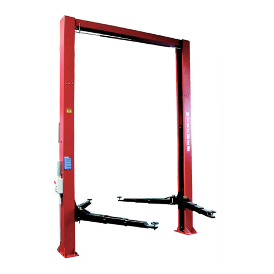
- Page 1 208I/5L SOLLEVATORE 2-POST ELETTROIDRAULICO ELECTRO-HYDRAULIC A 2 COLONNE LIFT...
- Page 3 Matricola N° Serial N° Anno di costruzione Year of manufacture COSTRUTTORE: MANUFACTURER: WERTHER INTERNATIONAL S.p.A. WERTHER INTERNATIONAL S.p.A. Sede centrale: Via F. BRUNELLESCHI, 12 Head office: Via F. BRUNELLESCHI, 12 42040 CADE’ (RE) - ITALY 42040 CADE’ (RE) - ITALY Telefono ++ / +522 / 9431 (r.a.)
-
Page 4: Table Of Contents
Indice Contents Imballaggio, trasporto Packing, transport and storage e stoccaggio Pag. 3 Page 3 Introduzione Pag. 4 Introduction Page 4 Cap.1 Descrizione della Chapter 1 Description macchina Pag. 6 of the machine Page 6 Cap.2 Specifiche tecniche Pag. 8 Chapter 2 Technical specifications Page 8... - Page 5 IMBALLAGGIO, TRASPORTO E PACKING, TRANSPORT AND STOCCAGGIO STORAGE LE OPERAZIONI DI IMBALLAGGIO, SOLLEVAMENTO, MOVI- MENTAZIONE, TRASPORTO E DISIMBALLO DEVONO ESSE- ALL PACKING, LIFTING, HANDLING, TRANSPORT AND RE AFFIDATE ESCLUSIVAMENTE A PERSONALE CHE SIA UNPACKING OPERATIONS ARE TO BE PERFORMED EXCLU- ESPERTO IN TALI OPERAZIONI E CHE CONOSCA BENE IL SIVELY BY EXPERT PERSONNEL WITH KNOWLEDGE OF THE SOLLEVATORE ED IL PRESENTE MANUALE...
- Page 6 APERTURA DEGLI IMBALLI OPENING THE CRATES All’arrivo verificare che la macchina non abbia subito danni durante When the crates arrive, check that the machine has not been il trasporto e che ci siano tutti i pezzi indicati nella lista di spedizio- damaged during transport and that all parts listed are present.
- Page 7 Il sollevamento, il trasporto, il disimballo, il montaggio, l’installazio- The lifting, transport, unpacking, assembling, installation, starting ne e la messa in servizio, la taratura e le registrazioni iniziali, la up, initial adjustment and testing, EXTRAORDINARY manutenzione STRAORDINARIA, la riparazione, la revisione, lo maintenance, repair, overhauls, transport and dismantling of the lift spostamento e lo smantellamento del sollevatore devono essere must be performed by specialised personnel from the LICENSED...
-
Page 8: Description Of The Machine
CAP.1. DESCRIZIONE DELLA CHAPTER 1 DESCRIPTION OF MACCHINA THE MACHINE Il sollevatore elettroidraulico a 2 colonne è fisso, cioè ancorato al The 2-post electro-hydraulic lift is a fixed installation. This means suolo ed è progettato e costruito per il sollevamento e lo staziona- that it is anchored to the ground and designed and built for lifting mento in quota di autoveicoli e furgoni. - Page 9 GRUPPI MOBILI (Vedere Fig.4) MOVING UNITS (see fig.4) Ciascuno è costituito da : Each unit consists of: · Un carrello (4) in lamiera di acciaio saldata, collegato nella parte · one carriage (4) built with welded steel plate, connected at the superiore ad un cilindro idraulico e nella parte inferiore, median- top to a hydraulic cylinder, and at the bottom, to the lift arms by te perni, ai bracci di sollevamento.
-
Page 10: Technical Specifications
CAP.2 SPECIFICHE TECNICHE CHAPTER. 2 TECHNICAL SPECIFICATIONS PORTATA:..........5000 Kg (49033 N) CAPACITY:.........5000 Kg (49033 N) Alt. max. sollevamento auto.......1965 mm Car max. lifting height ........1965 mm Alt. min. supporti sollevamento ......125 mm Lift min. stand height.......... 125 mm Larg. libera tra le colonne ........3000 mm Clearance between posts ........3000 mm Larg. - Page 11 POMPA della centralina idraulica: Hydraulic unit PUMP MOTORE MOTOR Trifase 3-ph. Tipo Type Modello 10A7,4X348N Model 10A7,4X348N Cilindrata 7.4 cm Size 7.4 cm Taratura valvola di massima 160 bar Relief valve set-up 160 bar OLIO Il serbatoio dell’ olio contiene olio idraulico a base minerale secon- The oil reservoir contains hydraulic mineral oil in accordance with do la normativa ISO/DIN 6743/4 con grado di contaminazione non ISO/DIN 6743/4 with a level of contamination that does not exceed...
- Page 12 SCHEMI ELETTRICI WIRING DIAGRAMS Fig.9 Schema elettrico TRIFASE THREE-PHASE wiring diagram. Descrizione Description Rif. Marca Articolo Q.tà Ref. Brand Article Q.ty C1-C2 ELM1-ELM2 Elettromagnete Electromagnet PR4TS-24DC/APC80 F6 SB Elettrovalvola Electro-valve OIL SISTEM 24VAC 50/60Hz ED100% Portafusibili Fuse carrier WEBER PCH10x38 + CH10x38 Limitatore di temperatura Temperature limiter Integrato nel motore / Integrate in the motor...
- Page 13 TIPI DI VEICOLI SOLLEVABILI E INGOMBRI VEHICLE WEIGHT AND SIZE Il sollevatore si adatta praticamente a tutti i veicoli di peso non su- Lift rack can be adapted to virtually all vehicles not heavier than periore a 5000 Kg e le cui dimensioni non eccedano quelle riporta- 5000 kg, the dimensions of which do not exceed the following.
-
Page 14: Safety
CAP.3 SICUREZZA CHAPTER 3 SAFETY E’ estremamente importante leggere questo capitolo attenta- It is vital to read this chapter of the manual carefully and from mente ed in ogni sua parte poichè contiene importanti infor- beginning to end as it contains important information mazioni sui rischi che operatore e manutentore possono cor- regarding the risks that the operator or maintenance fitter may rere in caso di un uso errato del ponte sollevatore. - Page 15 PRECAUZIONI GENERALI GENERAL PRECAUTIONS L’operatore ed il manutentore sono tenuti al rispetto delle prescri- The operator and the maintenance fitter are required to observe zioni contenute in leggi e norme antinfortunistiche vigenti nel paese the prescriptions of accident prevention legislation in force in the in cui è...
- Page 16 É estremamente importante posizionare il mezzo sul sollevatore in It is very important to position the vehicle on the lift so that the modo da avere una corretta ripartizione dei pesi sui bracci (Fig.15) weight is correctly distributed on the arms (fig.15). For persons and equipment safety, it is important that: Per la sicurezza delle persone e dei mezzi è...
- Page 17 · in caso di avaria completa dei microinterruttori, i carrelli si ferme- · If the hydraulic cylinder breaks, the safety wedges will trip (ref.1, rebbero pochi mm più in alto perché i cilindri idraulici andrebbero see.fig.18), located inside the posts (2). The wedges are pushed a fine corsa facendo intervenire la valvola di massima pressione by the spring (3) and immediately stop the carriages (4) preven- sulla centralina.
- Page 18 RISCHI DIRETTI ALLE PERSONE RISKS TO PERSONS In questo paragrafo verranno illustrati i rischi che operatore, manu- This paragraph illustrates risks to which the operator, maintenance tentore e chi si trova nell’area di lavoro del sollevatore, possono worker or any person near the operating area of the lift may be correre a causa di un uso non corretto del sollevatore stesso.
- Page 19 RISCHIO DI CADUTA DEL VEICOLO RISK OF VEHICLE FALLING FROM DAL SOLLEVATORE. LIFT Che può essere causato dal posizio- This risk could be caused by the in- namento non corretto del veicolo sui correct positioning of the vehicle on piattelli dei bracci, da un posiziona- the arm disk support plates (fig.25) mento non corretto del veicolo rispet- or incorrect positioning of the arm...
- Page 20 RISCHIO DI FOLGORAZIONE RISK OF ELECTRIC SHOCK Accanto a parti del sollevatore in cui Risk of electric shock in areas of the si trovano fili elettrici evitate getti d’ac- lift housing electrical wiring. qua, di vapore (da pulitrice a vapore), Do not use jets of water, steam (high di solventi o vernici nella zona del sol- pressure wash units), solvents or...
-
Page 21: Installation
CAP.4 INSTALLAZIONE CHAPTER 4 INSTALLATION QUESTE OPERAZIONI SONO DI COMPETENZA THE FOLLOWING OPERATIONS MUST BE ESCLUSIVA DEI TECNICI SPECIALIZZATI INCARI- PERFORMED EXCLUSIVELY BY SPECIALISED CATI DAL COSTRUTTORE O DAI RIVENDITORI TECHNICAL STAFF WITH AUTHORISATION AUTORIZZATI . FROM THE MANUFACTURER OR LICENSED SE EFFETTUATE DA ALTRE PERSONE POSSO- DEALER. - Page 22 PAVIMENTO FLOOR Il sollevatore deve essere installato su platea orizzontale di spes- The lift must be installed on a horizontal concrete bed with a mini- sore minimo 150 mm realizzata in calcestruzzo dosato con resi- mum thickness of 150 mm built and a resistance minimum 25 stenza min.di 25 N/mm N/mm Il pavimento deve inoltre essere piano e ben livellato (10 mm di tol-...
- Page 23 Fig.35 Fig.35A Fig.37 Fig.36 3 - Sollevare in verticale la co- 3 - Raise the command post lonna comando e posizionarla up and place it in the set as- nel punto di installazione pre- sembling point, paying atten- stabilito curando gli allinea- tion to the machine position menti col fabbricato.
- Page 24 10 - Prendere la trave superiore (1) (Vedere Fig.39) e montare ad 10 - Mount two pulleys, (2), one long spacer (3), two short ones (4) ognuna delle sue estremità: due puleggie (2), un distanziale lungo and one pin (5) on each end of the upper beam (1, see fig.39). (3), due distanziali corti (4) e il perno (5).
- Page 25 MONTAGGIO DELLE FUNI DI SINCRONISMO (Fig. 43). ASSEMBLING THE SYNCHRONOUS DEVICE CABLES (Fig.43) 1 - Verificare che i due carrelli siano in posizione completamente 1 - Check the two carriages are in a completely lowered position. abbassata. 2 - Prelevare una fune (1) dal rotolo e infilarne, dall’ alto verso il 2 - Take one cable (1) from the coil and put the threaded end (2) in basso, l’...
- Page 26 3-Orientare la testina del microinterruttore 3-Position the safety microswitch di sicurezza (6) fino a che fra questa e il head (6) until that between this and piattino (7) di azionamento del sensore vi the atarting sensor plate(7) there is a sia una distanza minima di 3 mm.(Fig.
- Page 27 COMPLETAMENTO DEL SISTEMA DI AZIONAMENTO DELLE SAFETY DEVICES ACTIVATING SYSTEM SICUREZZE. 1 - Controllare che i martelletti montati sulle colonne per l’ arresto 1 - Check that the safety wedges on the posts to stop the carriages dei carrelli (Vedere Fig.18 Rif.1), siano in ordine e non abbiano su- (See fig.18, ref.
- Page 28 ALLACCIAMENTO DELL’ IMPIANTO ELETTRICO ELECTRIC PLANT CONNECTION ATTENZIONE WARNING Le operazioni sottoelencate devono essere ese- The operations listed below must be performed guite da personale qualificato. by skilled personnel. 1) Prima del collegamento elettrico verificare che : 1) Before connecting the electric system, make sure that: ·...
- Page 29 4) Eseguire l’allacciamento di potenza e di comando alla morsettie- 4) Complete the voltage and command connections to the control ra del quadro, come indicato in fig.49 rif. “A”, inserendo il cavo nel- panel clamp box as shown in fig.49, ref.A. Insert the wire in the box la cassetta passando dal foro predisposto e seguendo lo schema through the pre-drilled hole, follow the wiring diagram as per pages dell’impianto elettrico come nelle pagine 10 e 11.
- Page 30 MONTAGGIO BRACCI E DISPOSITIVI DI BLOCCAGGIO-(Fig.53) ARM ASSEMBLING (Fig.53) 1 - Premendo il pulsante di salita, portare la parte inferiore dei 1 - Press the up push button, raise the carriages to a height of carrelli ad un’ altezza di circa 70 cm da terra, quindi premere il about 70 cm off the ground, then press the park push button, pulsante di stazionamento.
- Page 31 6 - Inserire lo spinotto (7) completo di rondella dentata (8) (preas- 6 - Insert the pin (7) complete with lock washer (8) (pre-assembled semblati dal costruttore) sull’ estremità scanalata della spina che by the manufacturer) on the grooved end of the pin that will project sporgerà...
- Page 32 COLLAUDI E CONTROLLI DA EFFETTUARE PRIMA TESTING AND CHECKS TO PERFORM BEFORE START-UP DELL’AVVIAMENTO VERIFICHE MECCANICHE MECHANICAL TESTS · Fissaggio e serraggio bulloni, raccordi e connessioni; · Attachment and tightness of bolts, fittings and connections; · Scorrimento libero delle parti mobili; ·...
-
Page 33: And Use
CAP.5 FUNZIONAMENTO ED CHAPTER 5 OPERATIONS AND USE The lift has the following commands (fig.55): I comandi del sollevatore sono i seguenti MAIN SWITCH (QS) (Fig.55): POSITION 0: The lift is not energised. It is INTERRUTTORE GENERALE (QS) possible to access the interior of the box POSIZIONE 0: Il sollevatore non è... -
Page 34: Maintenance
Cap.6 MANUTENZIONE CHAPTER 6. MAINTENANCE ATTENZIONE WARNING La manutenzione deve essere affidata ESCLUSI- Maintenance must be carried out ONLY BY SKIL- VAMENTE A PERSONALE ESPERTO CHE CONO- LED PERSONNEL WHO ARE VERY FAMILIAR SCA BENE IL SOLLEVATORE. WITH THE LIFT. Durante la manutenzione del sollevatore è... - Page 35 DOPO 1 SETTIMANA dall’installazione verificare: 1 WEEK AFTER the machine has been installed, check: · Il serraggio delle viti dei tasselli di fissaggio delle basi colonne. · the tightness of the posts bases connection anchor bolts. · Il serraggio delle viti di fissaggio della trave alle colonne. ·...
- Page 36 OLIO IMPIANTO IDRAULICO. HYDRAULIC PLANT OIL. Effettuare la sostituzione dell’olio, provvedendo come segue: Replace the oil, following the instructions listed below: · Abbassare il sollevatore fino alla quota minima (a terra). · Lower the lift to the minimum height (on the ground). ·...
-
Page 37: Troubleshooting
CAP.7 INCONVENIENTI E RIMEDI CHAPTER 7 TROUBLESHOOTING GUIDA ALLA RICERCA DEI GUASTI TROUBLESHOOTING GUIDE La ricerca dei guasti e gli eventuali interventi di riparazione ri- Troubleshooting and possible repairs require absolute chiedono il rispetto di TUTTE LE PRECAUZIONI DI SICUREZ- compliance with ALL THE SAFETY PRECAUTIONS indicated ZA indicate al capitolo 6 “MANUTENZIONE”... -
Page 38: Special Notes
APPENDICE A INFORMAZIONI APPENDIX A - SPECIAL NOTES PARTICOLARI SMALTIMENTO OLIO ESAUSTO DISPOSAL OF USED OIL L’olio esausto, che viene estratto dalla centralina e dall’impianto Used oil, which is removed from the power unit and from the plant durante il cambio olio, deve essere trattato come prodotto inqui- during an oil change, must be treated as a polluting product, in ac- nante pertanto da smaltire secondo le prescrizioni della legislazionl cordance with the legal prescriptions of the country in which the lift... - Page 39 COLONNE E TRAVE SUPERIORE POSTS AND UPPER BEAM...
- Page 40 CARRELLI E BRACCI CARRIAGES AND ARMS...
- Page 41 SICUREZZE SAFETY DEVICES...
- Page 42 QUADRO ELETTRICO TRIFASE THREE-PHASE CONTROL PANEL...
- Page 43 CENTRALINA OLEODINAMICA K3 OLEODYNAMIC CONTROL UNIT K3...
- Page 44 Part Code Sugg Descrizione Description A0101 VITE TE M5X10 UNI 5739 SCREW TE M5X10 UNI 5739 A0183 DADO M10 UNI 5588 NUT M10 UNI 5588 A0184 VITE TE M6X16 ZINCATA SCREW TE M6X16 UNI 5739 A0723 VITE TCEI M8X20 UNI 5931 SCREW TCEI M8X20 UNI 5931 B0030 VITE TE M8X16 UNI 5739...
- Page 45 B2078 INTERRUTTORE AUTOMATICO 10A TYPE C AUTOMATIC SWITCH 10A TYPE C B2082 COPERTURA PER MORSETTI 19.116.219.01 COVER FOR TYPE-LINE TERMINALS B2085 MORSETTIERA COMPLETA TRIFASE COMPLETE 3-PH. TERMINAL BOARD B2087 FERMACAVO Ø8 CABLE HOLDER Ø8 B2088 CILINDRO DI COMPRESSIONE COMPLETO COMPLETE COMPRESSION CYLINDER B2089 STANTUFFO PISTON...
- Page 46 B5422 SERBAT.L12 PVC NERO CENTR.K3 TANK B5423 POMPA 20 10A7,4X348N 7,4CC/REV PUMP B5424 TUBO ASPIRAZ.VERTIC.DIR.3/8" SUCTION PIPE B5425 FILTRO ASPIRAZIONE 3/8" AIR FILTER B5426 TUBO DI SCARICO VERTIC.L=400 DRAIN PIPE B5427 TAPPO DIN 908 3/8+RONDELL.RAME PLUG B5428 RONDELLA GROWER 8,4 UNI1751 ZB WASHER B5429 TAPPO DIN 908 1/4+RONDELL.RAME...
- Page 47 Konformitätserklärung - Déclaration de conformité Declaración de conformidad - Overensstemmelseserklæring Samsverserklæring - Överensstämmande intyg EG-Conformiteitsverklaring WERTHER INTERNATIONAL S.p.A. Via F.Brunelleschi, 12 42100 CADE’ (Reggio Emilia) Italy Tel.++/+522/9431 (r.a.) Fax ++/+522/941997 con la presente dichiariamo che il ponte sollevatore modello déclare par la presente que le pont elevateur modèle hereby we declare that the lift model hiermit erklären wir, daß...
Need help?
Do you have a question about the 208I/5L and is the answer not in the manual?
Questions and answers