Table of Contents
Advertisement
Advertisement
Table of Contents

Related Manuals for WERTHER INTERNATIONAL 232I


Summary of Contents for WERTHER INTERNATIONAL 232I
- Page 1 232I SOLLEVATORE 2-POST ELETTROIDRAULICO ELECTRO-HYDRAULIC LIFT A 2 COLONNE...
- Page 3 232I Modello Model Anno di costruzione Year of manufacture COSTRUTTORE: MANUFACTURER: WERTHER INTERNATIONAL S.p.A. WERTHER INTERNATIONAL S.p.A. Via F.BRUNELLESCHI Via F.BRUNELLESCHI 42040 CADE’ (RE) - ITALY 42040 CADE’ (RE) - ITALY Telefono ++ / +522 / 9431 (r.a.) Telefono ++ / +522 / 9431 (r.a.)
-
Page 4: Table Of Contents
Indice Contents Imballaggio, trasporto Packing, transport and storage e stoccaggio Pag. 4 Page 4 Introduzione Pag. 5 Introduction Page 5 Cap.1 Descrizione della Chapter 1 Description macchina Pag. 7 of the machine Page 7 Cap.2 Specifiche tecniche Pag. 9 Chapter 2 Technical specifications Page 9... - Page 5 IMBALLAGGIO, TRASPORTO E PACKING, TRANSPORT AND STOCCAGGIO STORAGE LE OPERAZIONI DI IMBALLAGGIO, SOLLEVAMENTO, MOVI- MENTAZIONE, TRASPORTO E DISIMBALLO DEVONO ESSERE ALL PACKING, LIFTING, HANDLING, TRANSPORT AND AFFIDATE ESCLUSIVAMENTE A PERSONALE CHE SIA UNPACKING OPERATIONS ARE TO BE PERFORMED EXCLU- ESPERTO IN TALI OPERAZIONI E CHE CONOSCA BENE IL SIVELY BY EXPERT PERSONNEL WITH KNOWLEDGE OF THE SOLLEVATORE ED IL PRESENTE MANUALE LIFT AND THE CONTENTS OF THIS MANUAL...
- Page 6 APERTURA DEGLI IMBALLI OPENING THE CRATES All’arrivo verificare che la macchina non abbia subito danni durante When the crates arrive, check that the machine has not been il trasporto e che ci siano tutti i pezzi indicati nella lista di spedizio - damaged during transport and that all parts listed are present.
- Page 7 Il sollevamento, il trasporto, il disimballo, il montaggio, l’installazio- The lifting, transport, unpacking, assembling, installation, starting ne e la messa in servizio, la taratura e le registrazioni iniziali, la up, initial adjustment and testing, EXTRAORDINARY manutenzione STRAORDINARIA, la riparazione, la revisione, lo maintenance, repair, overhauls, transport and dismantling of the lift spostamento e lo smantellamento del sollevatore devono essere must be performed by specialised personnel from the LICENSED...
-
Page 8: Description Of The Machine
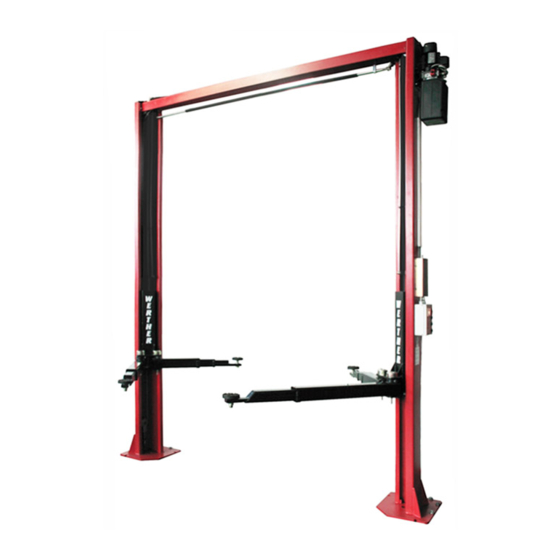
CAP.1. DESCRIZIONE DELLA CHAPTER 1 DESCRIPTION OF MACCHINA THE MACHINE Il sollevatore elettroidraulico a 2 colonne è fisso, cioè ancorato al The 2-post electro-hydraulic lift is a fixed installation. This means suolo ed è progettato e costruito per il sollevamento e lo staziona- that it is anchored to the ground and designed and built for lifting mento in quota di autoveicoli e furgoni. - Page 9 GRUPPI MOBILI (Vedere Fig.4) MOVING UNITS (see fig.4) Ciascuno è costituito da : Each unit consists of: · Un carrello (4) in lamiera di acciaio saldata, collegato nella parte · one carriage (4) built with welded steel plate, connected at the superiore ad un cilindro idraulico e nella parte inferiore, median- top to a hydraulic cylinder, and at the bottom, to the lift arms by te perni, ai bracci di sollevamento.
-
Page 10: Technical Specifications
CAP.2 SPECIFICHE TECNICHE CHAPTER. 2 TECHNICAL SPECIFICATIONS PORTATA: .............3200 Kg (31390 N) CAPACITY: ............3200 Kg (31390 N) Alt. max. sollevamento auto ..........1935 mm Car max. lifting height............1935 mm Alt. min. supporti sollevamento ........95 mm Lift min. stand height ............95 mm Larg. - Page 11 POMPA della centralina idraulica: Hydraulic unit PUMP MOTORE APPLICATO MOTOR Trifase Monofase 3-ph. Single-ph. Tipo Type Modello 10A5X348N 10A5X348N Model 10A5X348N 10A5X348N Cilindrata 5 cm 5 cm Size 5 cm 5 cm Taratura valvola di massima 200 bar 200 bar Relief valve set-up 200 bar 200 bar...
- Page 12 SCHEMI ELETTRICI WIRING DIAGRAMS Schema elettrico TRIFASE THREE-PHASE wiring diagram. Fig.9 Componenti impianto trifase 230V e 400V 230V and400V 3-phase plant parts Rif. Descrizione Description Marca Articolo Qt.à Ref. Brand Type Q.ty C1-C2 Elettromagneti Electromagnet PR4TS-24DC/APC80 F6 SB Elettrovalvola Solenoid-valve OIL SISTEM 24VAC 50/60Hz ED100% FU1-FU2...
- Page 13 Schema elettrico MONOFASE SINGLE-PHASE wiring diagram Fig.10 Componenti impianto monofase 230V 230V single-phase plant parts Rif. Descrizione Description Marca Articolo Qt.à Ref. Brand Type Q.ty C1-C2 Elettromagneti Electromagnet PR4TS-24DC/APC80 F6 SB Elettrovalvola Solenoid-valve OIL SISTEM 24VAC 50/60Hz ED100% FU1-FU2 Portafusibili Fuse carrier WEBER PCH1-10x38 + CH10x38...
- Page 14 TIPI DI VEICOLI SOLLEVABILI E INGOMBRI VEHICLE WEIGHT AND SIZE Il sollevatore si adatta praticamente a tutti i veicoli di peso non su- Lift rack can be adapted to virtually all vehicles not heavier than periore a 3200 Kg e le cui dimensioni non eccedano quelle riporta- 3200 kg, the dimensions of which do not exceed the following.
-
Page 15: Safety
CAP.3 SICUREZZA CHAPTER 3 SAFETY E’ estremamente importante leggere questo capitolo attenta- It is vital to read this chapter of the manual carefully and from mente ed in ogni sua parte poichè contiene importanti infor- beginning to end as it contains important information mazioni sui rischi che operatore e manutentore possono cor- regarding the risks that the operator or maintenance fitter may rere in caso di un uso errato del ponte sollevatore. - Page 16 PRECAUZIONI GENERALI GENERAL PRECAUTIONS L’operatore ed il manutentore sono tenuti al rispetto delle prescri- The operator and the maintenance fitter are required to observe zioni contenute in leggi e norme antinfortunistiche vigenti nel pae- the prescriptions of accident prevention legislation in force in the se in cui è...
- Page 17 É estremamente importante posizionare il mezzo sul sollevatore in It is very important to position the vehicle on the lift so that the modo da avere una corretta ripartizione dei pesi sui bracci (Fig.15) weight is correctly distributed on the arms (fig.15). For persons and equipment safety, it is important that: Per la sicurezza delle persone e dei mezzi è...
- Page 18 · nel caso vengano sollevati autoveicoli di altezza superiore a 1,5 · When vehicles higher than 1.5m are lifted, the rise is interrupted metri, la salita viene interrotta dalla “barra di finecorsa” (rif.1 by the “end-stroke bar “(ref.1, fig.19), which, pushed by the vehi- Fig.19) che, spinta dal veicolo, agisce sul microinterruttore cle, works on the limit switch (ref.2, fig.19).
- Page 19 RISCHI DIRETTI ALLE PERSONE RISKS TO PERSONS In questo paragrafo verranno illustrati i rischi che operatore, manu- This paragraph illustrates risks to which the operator, maintenance tentore e chi si trova nell’area di lavoro del sollevatore, possono worker or any person near the operating area of the lift may be correre a causa di un uso non corretto del sollevatore stesso.
- Page 20 RISCHIO DI CADUTA DEL VEICOLO DAL SOLLEVATORE. RISK OF VEHICLE FALLING FROM LIFT Che può essere causato dal posizionamento non corretto del vei- This risk could be caused by the incorrect positioning of the vehicle colo sui piattelli dei bracci, da un on the arm disk support plates posizionamento non corretto del (fig.24) or incorrect positioning of...
- Page 21 RISCHIO DI FOLGORAZIONE RISK OF ELECTRIC SHOCK Accanto a parti del sollevatore in cui Risk of electric shock in areas of si trovano fili elettrici evitate getti the lift housing electrical wiring. d’acqua, di vapore (da pulitrice a Do not use jets of water, steam vapore), di solventi o vernici nella (high pressure wash units), sol- zona del sollevatore ed in particolar...
-
Page 22: Installation
CAP.4 INSTALLAZIONE CHAPTER 4 INSTALLATION QUESTE OPERAZIONI SONO DI COMPETENZA THE FOLLOWING OPERATIONS MUST BE ESCLUSIVA DEI TECNICI SPECIALIZZATI INCARI- PERFORMED EXCLUSIVELY BY SPECIALISED CATI DAL COSTRUTTORE O DAI RIVENDITORI TECHNICAL STAFF WITH AUTHORISATION AUTORIZZATI . FROM THE MANUFACTURER OR LICENSED SE EFFETTUATE DA ALTRE PERSONE POSSO- DEALER. - Page 23 PAVIMENTO FLOOR Il sollevatore deve essere installato su platea orizzontale di spes- The lift must be installed on a horizontal concrete bed with a mini- sore minimo 150 mm (Fig.34) realizzata in calcestruzzo dosato con mum thickness of 150mm (Fig.34) built and a resistance minimum resistenza min di 25 N/mm2.
- Page 24 2 - Sollevare in verticale la colonna comando e posizionarla nel 2 - Raise the command post up and place it in the set assembling punto di installazione prestabilito curando gli allineamenti col fab- point, paying attention to the machine position in referece to the bricato.
- Page 25 8 - Prendere la trave superiore, im- 8 - Sling the upper beam with the bragandola con il mezzo di solleva- lifting unit, place it on top of the mento, posizionarla alla sommità posts and fix to the upper plate delle colonne e fissarla alla piastra with the 4 HH screws 8x25 (1) and superiore con le 4 viti TE M8x25 (1)
- Page 26 COMPLETAMENTO IMPIANTO IDRAULICO (Fig. 40). HYDRAULIC PLANT (Fig.40) 1 - Collegare il tubo (1) all’ interno della trave superiore coi raccordi 1 - Connect the pipe (1) to the inside part of the upper beam, using (2 e 3) ai due tubi (5 e 6), premontati all’ interno delle colonne e fittings 2 and 3 to the pipes 5 and 6.
- Page 27 COMPLETAMENTO DEL SISTEMA DI AZIONAMENTO DELLE SAFETY DEVICES ACTIVATING SYSTEM SICUREZZE. 1 - Controllare che i martelletti montati sulle colonne per l’ arresto 1 - Check that the safety wedges on the posts to stop the carriages dei carrelli (Vedere Fig.18 Rif.1), siano in ordine e non abbiano su- (See fig.18, ref.
- Page 28 ALLACCIAMENTO DELL’ IMPIANTO ELETTRICO ELECTRIC PLANT CONNECTION ATTENZIONE WARNING Le operazioni sottoelencate devono essere ese- The operations listed below must be performed guite da personale qualificato. by skilled personnel. 1) Prima del collegamento elettrico verificare che : 1) Before connecting the electric system, make sure that: ·...
- Page 29 4) Eseguire l’allacciamento di potenza e di comando alla morsettie- 4) Complete the voltage and command connections to the control ra del quadro, come indicato in fig.45 rif. “A”, inserendo il cavo nel- panel clamp box as shown in fig.45, ref.A. Insert the wire in the box la cassetta passando dal foro predisposto e seguendo lo schema through the pre-drilled drill, follow the wiring diagram as in pages dell’impianto elettrico come nelle pagine 11 e 12.
- Page 30 MONTAGGIO BRACCI E DISPOSITIVI DI BLOCCAGGIO-(Fig.49) ARM ASSEMBLING (Fig.49) 1 - Premendo il pulsante di salita, portare la parte inferiore dei 1 - Press the up push button, raise the carriages to a height of carrelli ad un’ altezza di circa 70 cm da terra, quindi premere il about 70 cm off the ground, then press the park push button, pulsante di stazionamento.
- Page 31 7 - Verificare il corretto funzionamento del dispositivo di bloccaggio 7 - Make sure that the arm locking device works correctly, pressing bracci, premendo verso l’ alto sulla prolunga del perno spingimolla the extension of the spring thrusting pin (1) upwards and turning e ruotando il braccio in uno dei 2 sensi, così...
- Page 32 COLLAUDI E CONTROLLI DA EFFETTUARE PRIMA TESTING AND CHECKS TO PERFORM BEFORE START-UP DELL’AVVIAMENTO VERIFICHE MECCANICHE MECHANICAL TESTS · Fissaggio e serraggio bulloni, raccordi e connessioni; · Attachment and tightness of bolts, fittings and connections; · Scorrimento libero delle parti mobili; ·...
-
Page 33: And Use
CAP.5 FUNZIONAMENTO ED CHAPTER 5 OPERATIONS AND USE The lift has the following commands (fig.52): I comandi del sollevatore sono i seguenti MAIN SWITCH (QS) (Fig.52): POSITION 0: The lift is not energised. It is INTERRUTTORE GENERALE (QS) possible to access the interior of the box POSIZIONE 0: Il sollevatore non è... -
Page 34: Maintenance
Cap.6 MANUTENZIONE CHAPTER 6. MAINTENANCE ATTENZIONE WARNING La manutenzione deve essere affidata ESCLUSI- Maintenance must be carried out ONLY BY SKIL- VAMENTE A PERSONALE ESPERTO CHE CONO- LED PERSONNEL WHO ARE VERY FAMILIAR SCA BENE IL SOLLEVATORE. WITH THE LIFT. Durante la manutenzione del sollevatore When performing maintenance on the è... - Page 35 DOPO 1 SETTIMANA dall’installazione verificare: 1 WEEK AFTER the machine has been installed, check: · Il serraggio delle viti dei tasselli di fissaggio delle basi colonne. · the tightness of the posts bases connection anchor bolts. · Il serraggio delle viti di fissaggio della trave alle colonne. ·...
- Page 36 OLIO IMPIANTO IDRAULICO. HYDRAULIC PLANT OIL. Effettuare la sostituzione dell’olio, provvedendo come segue: Replace the oil, following the instructions listed below: · Abbassare il sollevatore fino alla quota minima (a terra). · Lower the lift to the minimum height (on the ground). ·...
-
Page 37: Troubleshooting
CAP.7 INCONVENIENTI E RIMEDI CHAPTER 7 TROUBLESHOOTING GUIDA ALLA RICERCA DEI GUASTI TROUBLESHOOTING GUIDE La ricerca dei guasti e gli eventuali interventi di riparazione ri- Troubleshooting and possible repairs require absolute chiedono il rispetto di TUTTE LE PRECAUZIONI DI SICUREZ- compliance with ALL THE SAFETY PRECAUTIONS indicated ZA indicate al capitolo 6 “MANUTENZIONE”... -
Page 38: Special Notes
APPENDICE A INFORMAZIONI APPENDIX A - SPECIAL NOTES PARTICOLARI SMALTIMENTO OLIO ESAUSTO DISPOSAL OF USED OIL L’olio esausto, che viene estratto dalla centralina e dall’impianto Used oil, which is removed from the power unit and from the plant durante il cambio olio, deve essere trattato come prodotto inqui- during an oil change, must be treated as a polluting product, in ac- nante pertanto da smaltire secondo le prescrizioni della legislazionl cordance with the legal prescriptions of the country in which the lift... - Page 39 COLONNE E TRAVE SUPERIORE POSTS AND UPPER BEAM SÄULEN UND OBENER BALKEN COLONNES ET TRAVERSE SUPÉRIEURE COLUMNAS Y TRAVESAÑO SUPERIOR...
- Page 40 CARRELLI E BRACCI CARRIAGES AND ARMS SCHLITTEN UND ARME CHARIOTS ET BRAS CARROS Y BRAZOS...
- Page 41 SICUREZZE SAFETY DEVICES SICHERHEITSVORRICHTUNGEN DISPOSITIFS DE SÉCURITÉ DISPOSITIVOS DE SEGURIDAD...
- Page 42 QUADRO ELETTRICO TRIFASE THREE-PHASE CONTROL PANEL SCHALTTAFEL DREHSTROM COFFRET ÉLECTRIQUE TRIPHASÉ CUADRO ELECTRICO TRIFASICO...
- Page 43 QUADRO ELETTRICO MONOFASE SINGLE-PHASE CONTROL PANEL SCHALTTAFEL EINPHASENSTROM COFFRET ÉLECTRIQUE MONOPHASÉ CUADRO ELECTRICO MONOFASICO...
- Page 44 CENTRALINA OLEODINAMICA K3 OLEODYNAMIC CONTROL UNIT K3 OELDYNAMISCHES SCHALTGEHÄUSE K3 CENTRALE HYDRAULIQUE K3 CENTRALITA OLEODINÁMICA K3...
- Page 45 Part Code Sugg Descrizione Description Beschreibung Description Denominacion A0025 RACCORDO A “L” M G 1/8" - TUBO Ø8 MALE “L” CONNECTION 1/8" -TUBE Ø8 “L” ANSCHLUSSKEGEL 1/8" -ROHR Ø8 COUDE MÂLE G 1/8" - TUYAU Ø8 UNIÓN “L” MACHO G 1/8" - TUBO Ø8 A0101 VITE TE M5X10 UNI 5739 SCREW TE M5X10 UNI 5739...
- Page 46 B2032 CARTER PROTEZIONE PROTECTION CASING SCHÜTZUNGSGEHÄUSE CARTER CARTER PROTECCIÓN B2053 BUSSOLA PER BARRA FINECORSA BUSH FOR END-OF-STROKE BAR BUCHSE FÜR ENDANSCHLAGSTANGE BAGUE CASQUILLO B2158 TELERUTTORE 24V 50/60HZ CONTACTOR 24V 50/60HZ FERNSCHALTER 24V 50/60HZ TÉLÉRUPTEUR 24V 50/60HZ CONTACTO 24V 50/60HZ B2804 VITE TCEI M8X10 UNI 5931 SCREW TCEI M8X10 UNI 5931 SCHRAUBE TCEI M8X10 UNI 5931...
- Page 47 DADO BASSO M22X1,5 UNI 5589 ZB LOW NUT M22X1,5 UNI 5589 ZB MUTTER M22X1,5 UNI 5589 ZB ÉCROU M22X1,5 UNI 5589 ZB TUERCA M22X1,5 UNI 5589 ZB B5691 TUBO FLESSIBILE LG. 800 232I FLEXIBLE PIPE GELBER SCHLAUCH FLEXIBLE HAUTE TUBO B5692...
- Page 48 B5710 CANALA CON COPERCHIO 232I RACEWAY KANAL CANAL CANALETA B5711 CILINDRO COMPLETO 232I COMPLETE CYLINDRE ZYLINDER KOMPLETT VEREIN COMPLÈTE CILINDRO COMPLETO B5712 CILINDRO IDR.232I CYLINDER ZYLINDER VÉRIN CILINDRO B5713 PISTONE CILINDRO 232I PISTON KOLBEN PISTON PISTÓN B5714 TESTATA CILINDRO 232I...
- Page 49 FUSE CARRIER 10X38 WIMEX PORTE-FUSIBLE 10X38 WIMEX PCH B6511 PORTAFUSIBILE 10X38 WIMEX PCH1 SCHMELZSICHERUNGHALTER PORTAFUSIBLES 10X38 WIMEX PCH1 PCH10X38 10X38 B6513 PASSACAVO GEWISS PG 9 CABLE CLAMP GEWISS PG9 KABELDURCHGANG GEWISS PG 9 PASSE-CÂBLE GEWISS PG9 PASACABLE GEWISS PG9 B6514 PASSACAVO GEWISS PG11 CABLE CLAMP GEWISS PG11 KABELDURCHGANG GEWISS PG11...
- Page 50 Dichiarazione di conformità - Déclaration de conformité Declaration of Conformity - Konformitätserklärung Declaración de conformidad - Overensstemmelseserklæring Överensstämmande intyg - EG-Conformiteitsverklaring WERTHER INTERNATIONAL S.p.A. Via F.Brunelleschi, 12 42124 CADE’ (Reggio Emilia) Italy Tel.++/+522/9431 (r.a.) Fax ++/+522/941997 dichiariamo che il ponte sollevatore modello declara, que l’elevador modelo...
Need help?
Do you have a question about the 232I and is the answer not in the manual?
Questions and answers