Table of Contents
Advertisement
Quick Links
Advertisement
Table of Contents

Related Manuals for CLIVET SCHIARA 2


Summary of Contents for CLIVET SCHIARA 2
- Page 1 SCHIARA 2 IE2-Y series from 27M to 35M...
- Page 2 Indicates that the appliance uses a flammable refrigerant. WARRANTY The product CLIVET is covered by a conventional warranty, valid from the date of purchase of the appliance, the conditions of which are specified in the GENERAL CONDITIONS OF SALE available at www.clivet.com WARNING –...
- Page 3 INDEX General Details ..........4 4 Maintenance ........... 25 General warnings and safety rules 4.1 Cleaning the indoor unit 1.2 Description of MONOSplit system 4.2 Cleaning the air filter components 4.3 Cleaning Your Louver 1.3 Description of MULTISplit system 4.4 Cleaning the outdoor unit components 4.5 Extended periods of inactivity 1.4 Accessories...
-
Page 4: General Details
WARNING – This manual is the property of CLIVET and reproduction or transfer to third parties of the contents of this document is prohibited. All rights reserved. It is an integral part of the product; make sure that it is always supplied with the appliance, even in case of sale/transfer to another owner, so that it can be consulted by the user or by personnel authorized to carry out maintenance and repairs. - Page 5 General Details CAUTION DANGER – When connecting refrigerant piping,keep substances or gases other than the specified refrigerant from entering the unit. The presence of other gases or substances can reduce unit performance and cause an abnormal increase in pressure in the refrigeration cycle. This can lead to explosion hazards and resulting injuries. –...
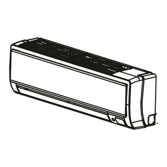
- Page 6 General Details Description of MONOSplit system components Fig. 1 Air inlet 6 Flexible drainage hose Air outlet 7 Electrical connection 1 Wall mounting plate 8 Refrigerant piping 2 Indoor unit 9 Outdoor unit power supply 3 Ventilation slit 10 Remote control 4 Filter 11 Remote control support 5 Outdoor unit...
- Page 7 General Details Description of MULTISplit system components 1 x 5 1 x 4 1 x 3 1 x 2 Fig. 2 Indoor unit Outdoor unit 1 Panel frame 10 Drain pipe, refrigerant connection pipe 2 Rear air intake grille 11 Connection cable 3 External panel 12 Stop valve 4 Purifier filter and air filter (on the back)
- Page 8 General Details Accessories The air conditioner is equipped with the following accessories. Use all specified installation components and accessories to install it. Incorrect installation may cause water leakage, electric shock and fire, or cause the unit to malfunction. Description Aspect Quantity Mounting plate Gusset...
- Page 9 General Details Identification The indoor unit and the outdoor unit can be identified by the serial number label that shows the technical and perfor- mance data of the unit and what is required by the legislation in force. Serial number label Indoor unit Fig.
-
Page 10: Installation
Installation 2 INSTALLATION Installation - preliminary warnings WARNING Product receiving Before installing the indoor unit, consult the label on the product package to check that the The appliance is supplied packed in several parcels. model number matches the model number of Handling must be carried out by appropriate means in the outdoor unit. -
Page 11: Indoor Unit Installation
Installation Indoor unit installation Refrigerant charge Minimum surface [kg] 41.5 2.4.1 Installation room 44.1 CAUTION 46,7 appliance must placed 49.4 well-ventilated room, with a minimum surface 52.2 area that varies according to the amount of refrigerant present. 55.1 58.0 To calculate the minimum area of the installation room, 7.956 61.0 proceed as described below:... - Page 12 Installation Please refer to the following diagram for wall and ceiling distances: Min 15 cm Min 12 cm Min 12 cm Min 2.3 m Fig. 4 Position of the display SCHIARA and remote control NOTE: The receiver must be left free of obstacles that could signal receiver.
-
Page 13: Mounting Plate
Installation 2.4.2 Mounting plate Correct orientation of the mounting plate MOUNTING PLATE DIMENSIONS The mounting plate is used to fix the indoor unit to the wall. Modello 27M - 35M Profilo dell’unità interna 410 mm Foro nel Foro nel muro muro 65 mm 65 mm... - Page 14 Installation 2.4.3 Preparation for connection pipes 1 Determine hole position according to the position of the mounting plate. To help you choose the optimal It is necessary to make a hole in the wall where the position, refer to point “Mounting plate dimensions”. refrigerant piping, drainage pipe and electrical cables The hole in the wall should have a minimum diameter that will connect the indoor unit to the outdoor unit will...
- Page 15 Installation 2.4.4 Preparation for refrigerant piping 4 Using scissors, cut the insulation sleeve so that about 15 cm of the refrigerant piping is exposed. This The refrigerant piping is located inside an insulating operation has a double utility: sleeve fixed on the back of the unit. It is necessary to –...
- Page 16 Installation 2.4.5 Drainage pipe IT IS PROHIBITED In the default configuration, the drainage pipe is connected to the left side of the unit (looking at the back – bend the drainage pipe upwards; of the unit). However, it can also be connected to the right –...
- Page 17 Installation 2.4.6 Electrical connections Cables with the following characteristics are required for power supply and communication between the indoor and outdoor units: Terminal block Power supplied Signal from outdoor Cover Indoor from outdoor unit unit unit n° cables/cross n° cables/cross section section 2 x 1.5mm...
- Page 18 Installation 2.4.7 Wrap the pipes and cables Connections in MONOSplit configuration It is necessary to wrap the coolant pipes, drainage pipe and electrical cables together; this reduces the space INDOOR unit terminal block Morsettiera unità INTERNA occupied, protects them and insulates them before passing them through the hole in the wall.
-
Page 19: Mounting The Indoor Unit
Installation 2.4.8 Mounting the indoor unit 3 Connect the drainage pipe and refrigerant piping (for CASE "A": If you have installed a new connection pipe instructions, see section “6 Notions on refrigerant to the outdoor unit, proceed as follows: piping connection” of the outdoor unit manual ). 1 Check that the ends of the coolant pipes are closed 4 Leave the pipe connection point exposed so that tightly to prevent dust or foreign materials from... -
Page 20: Description Of System Components
3 USE Meaning of the display codes Icon Description Description of system components It displays for 3 seconds when: • you set the start-up timer (TIMER ON) • Ioniser filter, TURBO,ECO, BREEZE AWAY,CASCADE or SILENCE functions are activated It displays for 3 seconds when: •... -
Page 21: Remote Control
Remote control ON/OFF MODE Unit switch-on/off button Presents the operating modes in the following order: AUTO » COOL » DRY » HEAT » FAN TEMP Increases the temperature by 0,5°C at a time. The maximum temperature is 30°C TEMP Reduces the temperature Used to select the fan speed by 0,5°C at a time. -
Page 22: Other Functions
3.4.1 Other functions When the unit is turned on, the ventilation slits automatically return to the last set angle. – Automatic restart – Detection of refrigerant leaks If the power supply to the unit is interrupted, the The indoor unit automatically displays "EC" when it unit will automatically restart with the last settings detects a refrigerant leak. - Page 23 BREEZE AWAY OPERATION 3.4.2 Airflow angle adjustment 1 Press the Breeze Away button on the remote control ADJUSTING THE VERTICAL AIR FLOW ANGLE to activate the avoiding direct air blowing on the body. With the unit turned on, use SWING button to adjust 2 Under Breeze Away operation, the system will adjust airflow direction.
-
Page 24: Manual Operation (Without Remote Control)
ADJUSTING THE HORIZONTAL AIR FLOW Manual operation (without remote ANGLE control) With the unit turned on, use the SWING button to adjust If the remote control does not work, the unit can be the direction of airflow. operated manually with the manual control button 1 To swing the ventilation slit continuously up and down, located on the indoor unit. -
Page 25: Maintenance
Maintenance 4 MAINTENANCE IT IS PROHIBITED It is good practice to periodically clean both the internal dry the filter by exposing it to direct sunlight. and external parts of the appliance. This guarantees its The filter may shrink proper functioning and durability. Carry out periodic maintenance of the appliance in 1 The air filter is under the panel. -
Page 26: Cleaning The Outdoor Unit
Maintenance Cleaning the outdoor unit 5 Rinse the filter with clean water and shake it to remove excess water. If the battery in the outdoor unit is clogged, remove the leaves and debris and then remove the dust with a jet of air or water. - Page 27 Maintenance Extended periods of inactivity If you do not plan to use the air conditioner for an extended period of time, proceed as follows: Clean all filters Activate the Ventilation mode until the unit is completely dry Turn off the unit and Remove the batteries disconnect it from the from the remote control...
-
Page 28: Troubleshooting
Maintenance Troubleshooting CAUTION DANGER If any of the following conditions occur, turn the unit off immediately. – The power cord is damaged or unusually hot. – You can smell burning. – The unit makes loud or abnormal noises. – A fuse blows or the circuit breaker trips frequently. –... - Page 29 Maintenance 4.7.2 Abnormalities and remedies If problems occur, please check the following before contacting a service centre. Anomalies Possible causes Remedies The set temperature may be higher than Set a lower temperature the room temperature The heat exchanger of the indoor or Clean the heat exchanger (Service Centre) outdoor unit is dirty Remove the filter and clean it following...
- Page 30 Maintenance Error codes displayed on the indoor unit display Error code Cause Timer light Defrost Filter cleaning reminder (power on display for 15 seconds) Active clean Filter replacement reminder(power on display for 15 seconds) Heating in room temperature under 8°C Forced cooling AP mode of WIFI connection Remote switched off...
- Page 31 Maintenance ERROR CODES DISPLAYED ON THE REMOTE CONTROL. Use the “Query mode” function on the remote control to display the alarms (see: technical manual special modes). Error code Description EH 00 / Indoor unit EEPROM parameter error EH 0A EL 01 Indoor / outdoor unit communication error EH 02 Zero-crossing signal detection error...
- Page 32 Maintenance PC 0F PFC module malfunction PC 0l Outdoor ambient tempreture too low PH 90 Evaporator coil temperature over high protection PH 91 Evaporator coil temperature over low Protection LC 05 Frequency limit caused by voltage LC 03 Frequency limit caused by current LC 02 Frequency limit caused by TP LC 01...
- Page 33 Disposal 5 DISPOSAL The manufacturer is registered on the National EEE Register, Professional WEEE: all WEEE which comes from something in compliance with implementation of Directive 2012/19/EU other than private households. and pertinent national regulations on electrical and electronic This equipment may contain: equipment waste.
- Page 34 Attachments 6 ATTACHMENTS Indoor unit wiring diagrams SERIES SIZE IE2-Y 27M - 35M...
-
Page 35: Conformance Statement
EGALE APPRESENTANTE CLIVET S.P.A. - Via Camp Lonc, 25 - Z.I. VILLAPAIERA - 32030 FELTRE (BL) – ITALIA Cap. Soc. Eur 20.000.000 i.v. – C.F. e reg.Impr. BL n°.00708410253 – R.E.A. n°.66577 –P.I./ VAT :IT 00708410253 Tel. +39 0439 3131 - Fax +39 0439 313300 – Sito Web : www.clivet.it... - Page 36 Attachments...
- Page 37 Attachments...
- Page 38 FOR 30 YEARS WE HAVE BEEN OFFERING SOLUTIONS FOR SUSTAINABLE COMFORT THE WELL-BEING OF PEOPLE AND THE ENVIRONMENT www.clivet.com sales and service CLIVET SPA Via Camp Lonc 25, Z.I. Villapaiera 32032 Feltre (BL) - Italy Tel. +39 0439 3131 - Fax +39 0439 313300 info@clivet.it...
-
Page 39: Outdoor Unit
OUTDOOR UNIT MONOSplit SCHIARA 2 ME2-Y series from 27M to 35M... - Page 40 Dear Customer, Thank you for choosing a CLIVET product. The SCHIARA 2 model which you have chosen, is a high performance product of advanced design and technology, high reliability and quality construction. We suggest that you entrust its management and maintenance to professionally qualified personnel you trust, who, when necessary, only use original spare parts.
- Page 41 INDEX General Details ..........4 5 Disposal ............24 General warnings and safety rules 6 Notions on refrigerant piping connection .. 25 1.2 Description of system components 6.1 Refrigerant piping connections 1.3 Accessories 6.1.1 Cut the pipes 1.4 Identification 6.1.2 Eliminate smudges 2 Installation ............
- Page 42 WARNING – This manual is the property of CLIVET and reproduction or transfer to third parties of the contents of this document is prohibited. All rights reserved. It is an integral part of the product; make sure that it is always supplied with the appliance, even in case of sale/transfer to another owner, so that it can be consulted by the user or by personnel authorized to carry out maintenance and repairs.
- Page 43 General Details CAUTION DANGER – When connecting refrigerant piping,keep substances or gases other than the specified refrigerant from entering the unit. The presence of other gases or substances can reduce unit performance and cause an abnormal increase in pressure in the refrigeration cycle. This can lead to explosion hazards and resulting injuries. –...
- Page 44 10 Remote control 3 Ventilation slit 11 Remote control support 4 Filter 12 Display LED SCHIARA 2 5 Outdoor unit WARNING The images in this manual are provided for illustrative purposes only. The appearance of your device may differ slightly from the illustrations shown here. Refer to the actual characteristics of the unit.
- Page 45 General Details Accessories The air conditioner is equipped with the following accessories. Use all specified installation components and accessories to install it. Incorrect installation may cause water leakage, electric shock and fire, or cause the unit to malfunction. Description Aspect Quantity Gasket Exhaust fitting...
- Page 46 General Details Identification The indoor unit and the outdoor unit can be identified by the serial number label that shows the technical and perfor- mance data of the unit and what is required by the legislation in force. Serial number label Indoor unit Serial number label Outdoor unit...
-
Page 47: Installation
Installation 2 INSTALLATION Installation - preliminary warnings WARNING Product receiving Before installing the indoor unit, consult the label on the product package to check that the The appliance is supplied packed in several parcels. model number matches the model number of Handling must be carried out by appropriate means in the outdoor unit. -
Page 48: Outdoor Unit Installation
Installation Outdoor unit installation SPECIAL CONSIDERATIONS FOR EXTREME WEATHER CONDITIONS If the unit is exposed to strong wind: 2.4.1 Installation Site Install the unit so that the air outlet fan is 90° to the direction of the wind. If necessary, place a barrier in front Before installing the outdoor unit, you must choose an of the unit to protect it from particularly strong winds. - Page 49 Installation 2.4.2 Installation of the drain connection 2.4.3 Mounting the outdoor unit Units with heat pump require a drain connection. Before The outdoor unit can be fixed to the floor or to a wall fixing the outdoor unit in place, you must install the drain mounted bracket.
-
Page 50: Electrical Connections
Installation 2.4.4 Electrical connections 4 Insert a nut at the end of each expansion block. 5 Hammer the expansion anchors into the holes made. Cables with the following characteristics are required to power the outdoor unit: 6 Remove the nuts from the expansion anchors and place the outdoor unit on the anchors. - Page 51 Installation The wiring diagram of the outdoor OUTSIDE unit terminal block Morsettiera unità ESTERNA unit is located inside the terminal box cover. 1(L) 2(N) Cover Screw signal power supply segnale alimentazione Fig. 7 dalla morsettiera 230V~50Hz from the terminal block of 4 Match the colours/labels of the cables to the labels dell’unità...
-
Page 52: Air Evacuation
Starting up the system 3 STARTING UP THE SYSTEM 3 Open the low pressure side of the manifold gauge assembly. Keep the high pressure side closed. 4 Activate the vacuum pump to evacuate the system. Air evacuation 5 Keep the vacuum pump running for at least 15 minutes, or until the low pressure gauge indicator The presence of air and foreign substances in the reads -76 cmHG (10... - Page 53 Starting up the system 3.1.1 Refrigerant charge DURING THE OPERATIONAL TEST Electrical dispersion control The unit is factory pre-charged with a sufficient quantity During the operational test, use an electrode and of refrigerant for pipe length up to 5 metres. multimeter to conduct a complete electrical leakage test.
- Page 54 Starting up the system 4 Leave each function active for 5 minutes and perform IF THE ROOM TEMPERATURE IS BELOW 16°C the following checks: If the room temperature is below 16°C, you cannot use the remote control to activate the cooling function (COOL). List of checks to be performed YES/NO In this case, you can use the MANUAL CONTROL button...
- Page 55 Maintenance 4 MAINTENANCE It is good practice to periodically clean both the internal and external parts of the appliance. This guarantees its proper functioning and durability. Carry out periodic maintenance of the appliance in accordance with the regulations in force. Maintenance must be carried out by qualified technical personnel.
- Page 56 Maintenance Anomalies Possible causes Remedies The amount of refrigerant in the system Check for leaks and top up the coolant (Service is excessive or insufficient Centre) Incompressible gas has entered or Evacuate the system and recharge the The unit starts or stops moisture has penetrated the system.
- Page 57 Maintenance Outdoor unit error messages Led signaling on the board (only on 35M unit) Flashing= error displayed on the indoor unit Slow flashing = stand-by LED on = unit ON Error code Description EC 51 Outdoor EEPROM malfunction EL 01 Indoor / outdoor units communication error PC 40 Communication malfunction between IPM board and outdoor main board...
- Page 58 Maintenance Operate safely with R32 refrigerant present Area ventilation FLAMMABLE MATERIAL Before working on the system or performing hot The refrigerant used inside this unit is operations, make sure the area is open or adequately flammable. A coolant leak that is exposed to ventilated.
- Page 59 Maintenance Repair of sealed components Leak detection methods The following leak detection methods are considered 10.1 While repairing sealed components, all electrical acceptable for systems containing flammable refrigerants. utilities must be disconnected from the equipment Electronic leak detectors can be used to detect before removing the sealing covers, etc.
- Page 60 Maintenance Charging operations 10 After filling the cylinders correctly and completing the procedure, transfer the cylinders and equipment from In addition to conventional charging procedures, it is the site as soon as possible and close all isolation recommended to follow the ensuing guidelines: valves on the equipment.
- Page 61 Maintenance Transport, marking and storage of units 1 Transport equipment containing flammable refrigerants – Follow applicable regulations related transporting these materials 2 Markings and signage on equipment – Observe the regulations in force 3 Disposing equipment containing flammable refrigerants – Comply with national regulations 4 Equipment storage –...
- Page 62 Disposal 5 DISPOSAL The manufacturer is registered on the National EEE Register, Professional WEEE: all WEEE which comes from something in compliance with implementation of Directive 2012/19/EU other than private households. and pertinent national regulations on electrical and electronic This equipment may contain: equipment waste.
-
Page 63: Refrigerant Piping Connections
Notions on refrigerant piping connection 6 NOTIONS ON REFRIGERANT PIPING CONNECTION The length of the refrigerant pipes affects performance and energy efficiency of the unit. The nominal efficiency is tested on units whose pipes are 5 meters long. For tropical areas, the maximum length of the coolant pipe must not exceed 10 metres. Refer to the following table for specifications on maximum pipe length and height difference Max equivalent length Max. - Page 64 Notions on refrigerant piping connection 6.1.3 Countersink the ends of the pipes Correct flaring is essential to perfectly seal the gasket. 1 After removing burrs from the cut pipe, seal the ends with PVC tape to prevent foreign materials from entering. 2 Wrap the pipe in an insulating material.
- Page 65 Notions on refrigerant piping connection 6.1.4 Connect the pipes Connecting the pipes to the indoor unit When connecting the coolant pipes, be careful not to use excessive torque or perform other operations that may 1 Align the centre of the two pipes to be connected. damage them.
-
Page 66: Connecting The Pipes To The Outdoor Unit
Notions on refrigerant piping connection Connecting the pipes to the outdoor unit 1 Unscrew the valve unit cover on the side of the outdoor unit. Valve group cover Fig. 22 2 Remove the protective caps from the valve ends. 3 Apply a little lubricating oil only to the inner surface of Fig. -
Page 67: Technical Data
Technical data 7 TECHNICAL DATA Technical features (MONOSplit) Unit Refrigerant piping inch Ø 1/4” Ø 1/4” Liquid line Ø 6.35 Ø 6.35 inch Ø 3/8” Ø 3/8” Gas line Ø 9.52 Ø 9.52 Max equivalent length Max. height difference outdoor unit / indoor unit ±10 ±10 Refrigerant pre-charge... - Page 68 Attachments 8 ATTACHMENTS Outdoor Unit Wiring Diagrams (27M - 35M) SERIES SIZE ME2-Y 27M - 35M...
- Page 69 Attachments...
- Page 70 FOR 30 YEARS WE HAVE BEEN OFFERING SOLUTIONS FOR SUSTAINABLE COMFORT THE WELL-BEING OF PEOPLE AND THE ENVIRONMENT www.clivet.com sales and service CLIVET SPA Via Camp Lonc 25, Z.I. Villapaiera 32032 Feltre (BL) - Italy Tel. +39 0439 3131 - Fax +39 0439 313300 info@clivet.it...
Need help?
Do you have a question about the SCHIARA 2 and is the answer not in the manual?
Questions and answers