Table of Contents
Advertisement
Quick Links
NANO130
®
®
ARM
Cortex
-M0
32-bit Microcontroller
®
NuMicro
Family
NuTiny-SDK-NANO130
User Manual
The information described in this document is the exclusive intellectual property of
Nuvoton Technology Corporation and shall not be reproduced without permission from Nuvoton.
Nuvoton is providing this document only for reference purposes of NuMicro microcontroller based system
design. Nuvoton assumes no responsibility for errors or omissions.
All data and specifications are subject to change without notice.
For additional information or questions, please contact: Nuvoton Technology Corporation.
www.nuvoton.com
Feb. 26, 2018
Page 1 of 19
Rev 1.02
Arrow.com.
Downloaded from
Advertisement
Table of Contents

Related Manuals for Nuvoton NuMicro NuTiny-SDK-NANO130


Summary of Contents for Nuvoton NuMicro NuTiny-SDK-NANO130
- Page 1 The information described in this document is the exclusive intellectual property of Nuvoton Technology Corporation and shall not be reproduced without permission from Nuvoton. Nuvoton is providing this document only for reference purposes of NuMicro microcontroller based system design. Nuvoton assumes no responsibility for errors or omissions.
-
Page 2: Table Of Contents
How to Start NuTiny-SDK-NANO130 on the Keil μVision IDE Software Download and Install ..........10 ® Keil uVision Nuvoton Nu-Link Driver Download and Install ........... 10 Hardware Setup ..................10 Example Program ..................11 How to Start NuTiny-SDK-NANO130 on the IAR Embedded Workbench ....12 IAR Embedded Workbench Software Download and Install ........ -
Page 3: Overview
NANO130 OVERVIEW ® NuTiny-SDK-NANO130 is the specific development tool for NuMicro NANO130 series. Users can use NuTiny-SDK-NANO130 to develop and verify the application program easily. NuTiny-SDK-NANO130 includes two portions. One is NuTiny-EVB-NANO130 and the other is Nu- Link-Me. NuTiny-EVB-NANO130 is the evaluation board and Nu-Link-Me is its Debug Adaptor. Thus, users do not need other additional ICE or debug equipments. -
Page 4: Nutiny-Sdk-Nano130 Introduction
To use Nu-Link-Me Debug adaptor with IAR or Keil, ® ® please refer to “Nuvoton NuMicro IAR ICE driver user manual “or Nuvoton NuMicro Keil ICE driver user manual” in detail. These two documents will be stored in the local hard disk when the user installs each driver. -
Page 5: Nutiny -Sdk-Nano130 Jumper Description
Voltage by JP2 Input Model 3 X: Unused. 2.1.2 Debug Connector JP4: Connector in target board (NuTiny-EVB-NANO130) for connecting with Nuvoton ICE adaptor (Nu-Link-Me) ICE JP8: Connector in ICE adaptor (Nu-Link-Me) for connecting with a target board (NuTiny-EVB-NANO130) 2.1.3... -
Page 6: Pin Assignment For Extended Connector
NANO130 Pin Assignment for Extended Connector NuTiny-EVB-NANO130 provides NANO130KE3BN on board and the extended connector for LQFP128-pin. Table 2-1 is the pin assignment for NANO130KE3BN. Pin No Pin Name Pin No Pin Name PE.13 PE.4/SPI0_MOSI0 PB.14/INT0/SC2_CD/SPI2_SS1 PE.3/SPI0_MISO0 PB.13/EBI_AD1 PE.2/SPI0_CLK PB.12/EBI_AD0/FCLKO PE.1/PWM1_CH3/SPI0_SS0 PE.0/PWM1_CH2/I2S_MCLK PC.13/SPI1_MOSI1/PWM1_CH1/SNOO... - Page 7 NANO130 LDO_CAP AVSS PA.0/AD0/SC2_CD PA.1/AD1/EBI_AD12 PA.2/AD2/EBI_AD11/UART1_RXD PA.3/AD3/EBI_AD10/UART1_TXD PA.4/AD4/EBI_AD9/SC2_PWR/I2C0_S PA.5/AD5/EBI_AD8/SC2_RST/I2C0_SC PA.6/AD6/EBI_AD7/TC3/SC2_CLK/PW M0_CH3 PA.7/AD7/EBI_AD6/TC2/SC2_DAT/PW M0_CH2 PE.12 VREF PE.11 PE.10 AVDD PD.0/UART1_RXD/SPI2_SS0/SC1_CLK PE.9 /AD8 PD.1/UART1_TXD/SPI2_CLK/SC1_DAT PE.8 /AD9 PD.2/UART1_RTSn/I2S_LRCLK/SPI2_ PE.7 MISO0/SC1_PWR/AD10 PD.3/UART1_CTSn/I2S_BCLK/SPI2_M OSI0/SC1_RST/AD11 PD.4/I2S_DI/SPI2_MISO1/SC1_CD PD.5/I2S_DO/SPI2_MOSI1 PC.7/DA1_OUT/EBI_AD5/TC1/PWM0_ PC.6/DA0_OUT/EBI_AD4/TC0/SC1_CD/ PB.0/UART0_RXD/SPI1_MOSI0 PWM0_CH0 PB.1/UART0_TXD/SPI1_MISO0 PC.15/EBI_AD3/TC0/PWM1_CH2 PB.2/UART0_RTSn/EBI_nWRL/SPI1_C PC.14/EBI_AD2/PWM1_CH3 PB.3/UART0_CTSn/EBI_nWRH/SPI1_S PB.15/INT1/SNOOPER/SC1_CD PD.6 Feb.
- Page 8 NANO130 PD.7 XT1_IN PD.14 XT1_OUT PD.15 PC.5/SPI0_MOSI1 nRESET PC.4/SPI0_MISO1 PC.3/SPI0_MOSI0/I2S_DO/SC1_RST PC.2/SPI0_MISO0/I2S_DI/SC1_PWR PC.1/SPI0_CLK/I2S_BCLK/SC1_DAT PC.0/SPI0_SS0/I2S_LRCLK/SC1_CLK PE.6 PF.4/I2C0_SDA PF.5/I2C0_SCL PE.5/PWM1_CH1 PVSS PB.11/PWM1_CH0/TM3/SC2_DAT/SPI0 PB.8/STADC/TM0/INT0/SC2_PWR _MISO0 PB.10/SPI0_SS1/TM2/SC2_CLK/SPI0_ PE.15 MOSI0 PB.9/SPI1_SS1/TM1/SC2_RST/INT0 PE.14 Table 2-1 Pin Assignment for NANO130 Feb. 26, 2018 Page 8 of 19 Rev 1.02 Arrow.com.
-
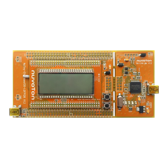
Page 9: Nutiny-Sdk-Nano130 Pcb Placement
NANO130 NuTiny-SDK-NANO130 PCB Placement Users can refer to Figure 2-2 for the NuTiny-SDK-NANO130 PCB placement and Figure 2-4 for the NuTiny-SDK-NANO130_TNLCD PCB placement. Figure 2-3 NuTiny-SDK-NANO130 PCB Placement Figure 2-4 NuTiny-SDK-NANO130_TNLCD PCB Placement Feb. 26, 2018 Page 9 of 19 Rev 1.02 Arrow.com. -
Page 10: How To Start Nutiny-Sdk-Nano130 On The Keil Μvision Ide
IDE Software Download and Install ® μ Please visit the Keil company website (http://www.keil.com) to download the Keil Vision and install the RVMDK. Nuvoton Nu-Link Driver Download and Install ® Please visit the Nuvoton company NuMicro website (http://www.nuvoton.com/NuMicro) to ® ®... -
Page 11: Example Program
NANO130 Example Program This example demonstrates the ease of downloading and debugging an application on a NuTiny- SDK-NANO130 board. It can be found on Figure 3-2 list directory and downloaded from Nuvoton ® NuMicro website. C:\Nuvoton\BSP Library\Nano100B_Series_BSP_CMSIS_v3.02.002\SampleCode\NUTINY-EVB- Directory NANO130\LCD_DEMO\KEIL Project... -
Page 12: How To Start Nutiny-Sdk-Nano130 On The Iar Embedded Workbench
IAR Embedded Workbench Software Download and Install Please connect to IAR company website (http://www.iar.com) to download the IAR Embedded Workbench and install the EWARM. Nuvoton Nu-Link Driver Download and Install ® Please visit the Nuvoton company NuMicro website (http://www.nuvoton.com/NuMicro ) to ®... -
Page 13: Example Program
Project File Figure 4-2 Example Directory To use this example: Connects the NuTuny-SDK-NANO130_TNLCD to NuTiny-SDK-NANO130. The LCD panel will display a NUVOTON logo. Project – Download and Debug Start IAR Embedded Workbench Program the application code into on-chip Flash ROM ... -
Page 14: Nutiny-Sdk-Nano130 Schematic
NANO130 NUTINY-SDK-NANO130 SCHEMATIC NuTiny-EVB-NANO130 Schematic VDD33 PIN[1..128] 0603R TICE_DAT TICE_DAT TICE_RST TICE_CLK PIN1 PIN65 TICE_CLK TICE_RST DVDD DVDD PIN2 PIN66 TICE_RST PIN3 PIN67 PUSH BUTTON 10uF/10V PIN71 nINT0 PIN4 PIN68 PIN5 PIN69 TANT-A PIN6 PIN70 PIN7 PIN71 0.1uF 0.1uF C0603 C0603 C0603 PIN8... -
Page 15: Gpio For 128 Pin Schematic
NANO130 GPIO for 128 pin Schematic PIN[1..128] PIN1 PIN33 PIN65 PIN97 PIN2 PIN34 PIN66 PIN98 PIN3 PIN35 PIN67 PIN99 PIN4 PIN36 PIN68 PIN100 JP11 PIN5 PIN37 PIN69 PIN101 PIN6 PIN38 PIN70 PIN102 RT9164A-3.3V HEADER 16PX2 PIN7 PIN39 PIN71 PIN103 PIN8 PIN40 PIN72 PIN104... -
Page 16: Nu-Link-Me Schematic
NANO130 Nu-Link-Me Schematic VCC33 VCC33 VCC33 VCC33 iceD2 SS24A iceD3 RTIDA1 RICK1 RB060L SS24A 100K 100K VCC33 AVDD ICE CONNECT IF RB060L 0603R 0603R iceJP9 iceL4 ICE_DAT RT9164A-3.3V ICER18 ICE_CLK ICE_RST L0603 0603R VCC33(A) VCC33 USBVBUS iceL5 HEADER 5PX1 iceJP8 HEADER 5PX1 TICE_DAT TICE_DAT... -
Page 17: 4X42 Tn Lcd Schematic
NANO130 NuTiny-SDK-NANO130_TNLCD Schematic HOLDER 16PX2, 2.00mm PIN51 SEG0 COM3 PIN52 PIN50 SEG1 COM2 PIN53 PIN49 SEG2 COM1 PIN54 PIN48 SEG3 COM0 PIN55 PIN1 PIN2 PIN47 SEG4 SEG39 PIN93 PIN96 PIN95 PIN3 PIN4 PIN46 SEG5 SEG38 PIN94 PIN94 PIN93 PIN45 SEG6 PIN44 SEG7 SEG37... -
Page 18: Revision History
NANO130 REVISION HISTORY Date Revision Description 2012.10.16 1.00 Initially issued. Change the value of C7 and C8 in the schematics 2013.01.08 1.01 from 10 pF to 6 pF. Updated the figure of NuTiny-SDK-NANO130 PCB Board in chapter 1. Updated th descriptions in chapter 2. 2018.02.26 1.02 Updated the example program descriptions in... - Page 19 NANO130 Important Notice Nuvoton Products are neither intended nor warranted for usage in systems or equipment, any malfunction or failure of which may cause loss of human life, bodily injury or severe property damage. Such applications are deemed, “Insecure Usage”.
Need help?
Do you have a question about the NuMicro NuTiny-SDK-NANO130 and is the answer not in the manual?
Questions and answers