
Related Manuals for Hatz Diesel 3H50


Summary of Contents for Hatz Diesel 3H50
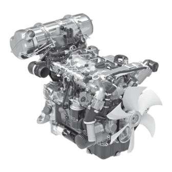
- Page 1 CREATING POWER SOLUTIONS. 3H50 | 4H50 MANUAL for diesel engine Hatz Diesel www.hatz-diesel.com...
-
Page 3: Table Of Contents
3H50, 4H50 / 06 - Rev. 00 Table of contents Table of contents Legal notices...................... 5 General information..................... 6 Safety ........................ 7 General information...................... 7 3.1.1 Intended use ........................ 7 3.1.2 Machine user or machine manufacturer obligations ............ 8 3.1.3 Representation of safety notes .................... 9 3.1.4 Meaning of safety symbols.................... 10... - Page 4 Table of contents 3H50, 4H50 / 06 - Rev. 00 Check the oil level ...................... 70 Refueling .......................... 72 Regenerating the diesel particulate filter................ 73 Maintenance ....................... 79 General maintenance instructions.................. 79 Maintenance work ...................... 80 8.2.1 Maintenance plan....................... 80 8.2.2 Additional work on the Silent Pack.................. 83 8.2.3...
-
Page 5: Legal Notices
3H50, 4H50 / 06 - Rev. 00 Legal notices Legal notices Contact data © 2023 Motorenfabrik Hatz Ernst-Hatz-Straße 16 94099 Ruhstorf Germany Tel. +49 (0)8531 319-0 Fax +49 (0)8531 319-418 marketing@hatz-diesel.de www.hatz-diesel.com All rights reserved! Copyright The copyright for this manual rests entirely with Motorenfabrik HATZ, Ruh- storf. -
Page 6: General Information
General information 3H50, 4H50 / 06 - Rev. 00 General information Information on the document This manual was created with due care. It is exclusively intended to offer a technical description of the machine and to provide instructions on commis- sioning, operating and maintaining the machine. -
Page 7: Safety
3H50, 4H50 / 06 - Rev. 00 Safety Safety General information Introduction This chapter contains the information you need to work safely with this ma- chine. To prevent accidents and damage to the machine, it is imperative that these safety instructions be followed. -
Page 8: Machine User Or Machine Manufacturer Obligations
Machine manufacturer obligations If you have an engine that is not yet installed in a machine, it is imperative that you follow the Assembly Instructions for HATZ Diesel Engines be- fore installing the engine. These assembly instructions contain important in- formation on how to safely install the engine and are available at your near- est HATZ service station. -
Page 9: Representation Of Safety Notes
3H50, 4H50 / 06 - Rev. 00 Safety All work performed on the machine must be in compliance with the informa- tion provided in this manual. Storing this manual This manual is an integral component of the machine (also when being sold). -
Page 10: Meaning Of Safety Symbols
Safety 3H50, 4H50 / 06 - Rev. 00 Signal words Signal words identify the magnitude of the risk and the seriousness of possi- ble injury: Danger symbol/ Meaning signal word This signal word is used to indicate imminently DANGER dangerous situations which, if not avoided, will lead to serious injury or death. - Page 11 3H50, 4H50 / 06 - Rev. 00 Safety Symbol Meaning Warning of flammable substances! Warning of explosive substances! Warning of toxic engine exhaust! Warning of corrosive substances! Warning of heavy loads! Warning of environmental damage! Comply with this manual or additional documentation from other manufacturers or the operator.
-
Page 12: Safety Notes
Safety 3H50, 4H50 / 06 - Rev. 00 Safety notes 3.2.1 Operational safety Introduction This chapter contains all of the important safety instructions for personal pro- tection and for safe and reliable operation. Additional, task-related safety in- structions can be found at the beginning of each chapter. - Page 13 3H50, 4H50 / 06 - Rev. 00 Safety Personal protective Pictogram Function equipment Safety shoes Safety shoes offer protection against: ▪ Slipping ▪ Falling objects Hearing protection Hearing protection offers protec- tion against ear injuries due to excessive and constant noise.
- Page 14 Safety 3H50, 4H50 / 06 - Rev. 00 Safety equipment Safety equipment must not be modified and must not be rendered ineffective during normal operation. General safety instructions DANGER Danger to life and danger of injury due to failure to follow the warnings on the machine and in this manual.
-
Page 15: Machine-Specific Safety Instructions For Operation
If you have an engine that is not yet installed in a machine, it is imperative that you follow the Assembly Instructions for HATZ Diesel Engines be- fore installing the engine. These Assembly Instructions contain important information on safe installa- tion. -
Page 16: Machine-Specific Safety Instructions For Maintenance Work
Safety 3H50, 4H50 / 06 - Rev. 00 DANGER Fire hazard from fuel. Leaked or spilled fuel can ignite on hot engine parts and cause serious burn injuries. ▪ Only refuel when the engine is switched off and has cooled down. - Page 17 3H50, 4H50 / 06 - Rev. 00 Safety Replacing parts ▪ When replacing defective components, we recommend that you use Hatz original spare parts (see chapter 2 General information, page 6). ▪ When disposing of parts that can no longer be used, do so in accordance with local environmental regulations or send them to a recycling center.
-
Page 18: Electrical Equipment
Safety 3H50, 4H50 / 06 - Rev. 00 CAUTION Danger of burns. There is a danger of burns when working on a hot engine. ▪ Let the engine cool before maintenance. 3.2.4 Electrical equipment Safety notes DANGER Danger to life, danger of injury or danger of property dam- age due to incorrect use of batteries. -
Page 19: Labels
3H50, 4H50 / 06 - Rev. 00 Safety CAUTION Danger of chemical burns Chemical burns can occur when using batteries for the electrical operation. ▪ Protect your eyes, skin, and clothing from corrosive battery acid. ▪ Immediately rinse areas affected by splashed acid with clear water and consult a physician if necessary. - Page 20 Safety 3H50, 4H50 / 06 - Rev. 00 sign Meaning Warning of hot surfaces! Cleaning with a high pressure cleaner is prohibited! ▪ Do not spray the Hatz instrument box with a high-pressure water jet. Warning labels and information signs on the battery (option)
-
Page 21: Technical Data
3H50, 4H50 / 06 - Rev. 00 Technical data Technical data Engine information and filling quantities Type 3H50 4H50 Type Liquid-cooled four stroke diesel engine Combustion system Direct injection Number of cylinders Bore/Stroke 84 / 88 84 / 88 Displacement... - Page 22 Technical data 3H50, 4H50 / 06 - Rev. 00 Engine specifications Model Description With turbocharger. with turbocharger and charge air cooling. With turbocharger, charge air cooling, cooled ex- haust gas recirculation (EGR) and diesel oxidation catalyst (DOC) TICD With turbocharger, charge air cooling, cooled ex- haust gas recirculation (EGR), diesel oxidation cata- lyst (DOC) and diesel particulate filter (DPF).
- Page 23 3H50, 4H50 / 06 - Rev. 00 Technical data Coolant filling quantities (engines with Hatz cooler) Hatz cooler With external expansion With integrated expansion tank tank Type Filling quantity in liters * 3H50 T – 3H50 TI 12,6 13.3 3H50 TIC 12,6 13.3...
- Page 24 Technical data 3H50, 4H50 / 06 - Rev. 00 Screw tightening torque Designation Oil drain screw Drain screw on engine cooler Drain screw on charge air cooler Connection and fixing screws (M10) for protective guard (engine specification TI, TIC, TICD)
-
Page 25: Engine Type Plate
3H50, 4H50 / 06 - Rev. 00 Technical data Engine type plate EMISSION CONTROL INFORMATION MOTORENFABRIK HATZ GMBH KG ¬ D-94099 RUHSTORF www.hatz-diesel.com Model: Build: S/N: Power: Displ: Eng.Fam: Emission Control System: Power Category: ULTRA LOW SULFUR DIESEL FUEL ONLY. - Page 26 Technical data 3H50, 4H50 / 06 - Rev. 00 4.2.1 Engine serial number Breakdown of the engine serial number 133 11 15 123456 Engine type number Engine serial number Model year Fabrication number (consecutive) Engine type number The engine type number makes it possible to see if the engine is equipped with a diesel oxidation catalyst (DOC).
-
Page 27: Engine Oil
3H50, 4H50 / 06 - Rev. 00 Technical data Engine oil Oil quality All oil brands that meet at least one of the following specifications are suit- able: Engines with diesel oxidation catalyst (DOC) (for details, see section 4.2.1 Engine serial number, page 26). -
Page 28: Coolant
Technical data 3H50, 4H50 / 06 - Rev. 00 CAUTION Engine damage from unsuitable engine oil. Unsuitable engine oil considerably reduces engine service life. Only use engine oil that fulfills the specifications stipulated above. Coolant Introduction Liquid-cooled engines require a coolant specified by HATZ for engine cool- ing. - Page 29 3H50, 4H50 / 06 - Rev. 00 Technical data Recommended cooler coolant Product name Container HATZ order no. H-series Coolant 5 liters 0000 055 413 00 The H-series Coolant concentrate is exactly matched to the requirements of your HATZ diesel engine.
- Page 30 Technical data 3H50, 4H50 / 06 - Rev. 00 manufacturer Product name Gulf Gulf Eurocool G-40 Concentrate Huiles Berliet RTO Maxigel Plus S.A. INA MAZIVA INA Antifriz BS Super Ltd. JMC coolant JM12 Plus Kemetyl CARIX COOLANT PREMIUM LONGLIFE, GLYCOCOOL LONGLIFE PREMIUM ANTIF.774 D-F, Shell Premium...
- Page 31 3H50, 4H50 / 06 - Rev. 00 Technical data manufacturer Product name Raloy Antifreeze Raloy G-30, Raloy Anticongelante Concentrate Lubricantes (G40) Recochem HD Expert™ Endurance REPSOL LU- REPSOL ANTI.REF.ORGANICO MAXIMUM QUALITY, BRICANTES REPSOL GUARD REFRIGERANTE ORGANICO MQ AG40 Liquido Refrigerante Sinopec SINOPEC Antifreeze B25.5...
-
Page 32: Fuel
Technical data 3H50, 4H50 / 06 - Rev. 00 The following values must not be exceeded: Water quality Max. Water hardness (°dGH) Water hardness (mmol/l) Chloride content (ppm) Sulfate content (ppm) The coolant mixture ratio must not be below or exceed the following concen-... - Page 33 3H50, 4H50 / 06 - Rev. 00 Technical data CAUTION Danger of malfunctions due to old fuel. When diesel fuel is stored in a fuel tank or canister for lengthy periods, deposits may form on account of fuel aging. These de- posits result in malfunctions due to clogged fuel filters and dam- age to the injection system.
-
Page 34: Engine Overview
Engine overview 3H50, 4H50 / 06 - Rev. 00 Engine overview Designation of components Model – TIC intake side Intake opening for combustion air Oil filler plug, top (option) Oil filter Main fuel filter Drain screw with integrated water in fuel sensor... - Page 35 3H50, 4H50 / 06 - Rev. 00 Engine overview Fuel prefilter Electric fuel pump Starter (low mounting position) Dipstick Oil filler plug, bottom Engine type plate Oil filler plug, middle (option) Crankcase ventilation HATZ Manual...
- Page 36 Engine overview 3H50, 4H50 / 06 - Rev. 00 Model – TIC/TICD exhaust side Lifting eyes DPF system with diesel oxidation catalytic converter and diesel particulate filter (TICD model) Turbocharger Engine foot Diesel oxidation catalytic converter DOC (TIC model) Exhaust outlet...
- Page 37 3H50, 4H50 / 06 - Rev. 00 Engine overview Model – OPU intake side NOTICE The Open Power Unit (OPU) is a complete system which, in ad- dition to the engine, also includes all of the components required for cooling.
- Page 38 Engine overview 3H50, 4H50 / 06 - Rev. 00 Air filter (optional) Dust discharge valve Lifting eyes Engine control unit Plug holder with integrated relay, glow control unit and fuse holder Oil filter Main fuel filter Drain screw with integrated water in fuel sensor...
- Page 39 3H50, 4H50 / 06 - Rev. 00 Engine overview Model – OPU exhaust side Radiator with integrated expansion tank Sealing cap for coolant Oil filler plug, top (option) Turbocharger Diesel oxidation catalyst (DOC) Exhaust outlet Starter (high mounting position) Three phase alternator...
-
Page 40: Hatz Smart Panel (Hsp)
Engine overview 3H50, 4H50 / 06 - Rev. 00 Encapsulated model – Silent Pack NOTICE The Silent Pack is an Open Power Unit (OPU) that is sur- rounded by a noise and weather protection capsule. The mainte- nance covers (4) and (6) can be removed for daily maintenance work. - Page 41 3H50, 4H50 / 06 - Rev. 00 Engine overview Fuel prefilter Speed control (option) Engine type plate Ignition lock Components of the electronic engine control unit Pos. Designation Figure Crankshaft speed sensor HATZ Manual...
- Page 42 Engine overview 3H50, 4H50 / 06 - Rev. 00 Pos. Designation Figure Air filter differential pressure sensor Rail pressure sensor Rail pressure control valve EGR valve Coolant level sensor (integrated in external expan- sion tank) Coolant temperature sensor Coolant level sensor (for cooler with integrated ex-...
- Page 43 3H50, 4H50 / 06 - Rev. 00 Engine overview Pos. Designation Figure Air mass meter (TICD model) Camshaft sensor Differential pressure sensor (TICD model) Exhaust gas temperature sensor (TICD model) Low fuel pressure and fuel temperature sensor Water in fuel sensor...
- Page 44 Engine overview 3H50, 4H50 / 06 - Rev. 00 Fuses Overview - fuse assignment Pos. Consumer Fuse Central electrical system Signal inputs for control unit 5 A Fuel pump 10 A Glow plugs 40 A Voltage supply for control unit 15 A Ignition, terminal 15 10 A...
-
Page 45: Main Menu
3H50, 4H50 / 06 - Rev. 00 Engine overview Hatz Smart Panel (HSP) Overview Housing Function keys Display 5.3.1 Main menu Overview 1950 1150 1147 3000 STOP 65.0 13.9 12.4 °C Preselected engine speed indicator Actual engine speed Warning and indicator lamps... - Page 46 Engine overview 3H50, 4H50 / 06 - Rev. 00 Button for START – STOP Only in model "Engine start/engine stop via CAN bus" Menu selection key Button for calling up the diagnostic trouble codes Button for speed increase Button for speed reduction...
- Page 47 3H50, 4H50 / 06 - Rev. 00 Engine overview Symbol Meaning Speed increase Only in model with variable speed. Speed reduction Only in model with variable speed. Warning and indicator lamps: Pre-glow indicator Lights up at engine temperatures below 30 °C. Start the engine after the indicator has gone out.
- Page 48 Engine overview 3H50, 4H50 / 06 - Rev. 00 Symbol Meaning Engine malfunction This indicator lights up if there an engine malfunction. Change to the diagnostic trouble code page for a fault diagnosis; see sec- tion 9.2 Diagnostic trouble codes in case of engine malfunctions, page 130.
-
Page 49: Menu - Current Values
3H50, 4H50 / 06 - Rev. 00 Engine overview Symbol Meaning Regeneration of the diesel particulate filter was blocked. Orange → Soot particle filter load is high Service interval indicator The 500-hour service is due. After completion of the service work, reset the service interval indicator, see section 8.2.18 Re-... -
Page 50: Menu - General Settings
Engine overview 3H50, 4H50 / 06 - Rev. 00 Procedure Step Activity Press the button for the menu selection (1). The display changes to the "Current Values" menu. This menu consists of 3 pages. Select the desired page using the buttons (2) and (3). - Page 51 3H50, 4H50 / 06 - Rev. 00 Engine overview Procedure Step Activity Figure In the main menu, Main menu press the menu selec- tion button (1) 3x. The display changes to the 1950 Page selection menu. 1150 1147 3000 65.0 13.9 12.4 °C...
- Page 52 Engine overview 3H50, 4H50 / 06 - Rev. 00 Step Activity Figure Using buttons (2 or 3), Language select the desired lan- guage and confirm with General Settings OK (button 4). Proceed Brightness in the same way to > Language English...
-
Page 53: Transport, Installation And Commissioning
3H50, 4H50 / 06 - Rev. 00 Transport, installation and commissioning Transport, installation and commissioning Transport Safety notes WARNING Danger of injury from improper lifting and transport. Danger of crushing from the engine falling or tipping. ▪ The machine may only be lifted using the lifting points (1). - Page 54 Transport, installation and commissioning 3H50, 4H50 / 06 - Rev. 00 Access to the lifting eyes with the Silent Pack Overview Control side maintenance lid Top maintenance cover Bracket for the air filter Clamp-type fasteners for control side maintenance cover...
- Page 55 3H50, 4H50 / 06 - Rev. 00 Transport, installation and commissioning Sealing lip Fixing screws for bracket for the air filter (4 pieces) Procedure Step Activity Turn clamp-type fasteners (1) to the left up to the stop. Tip main- tenance cover on the bottom to the outside and lift away up- wards.
-
Page 56: Installation Notes
HATZ service station. For contact data, see chapter 1 Legal no- tices, page 5 or www.hatz-diesel.com. Installation notes HATZ diesel engines are efficient, robust, and have a long service life. Therefore, they are usually installed in machines that are used for commer- cial purposes. -
Page 57: Preparations For Commissioning
3H50, 4H50 / 06 - Rev. 00 Transport, installation and commissioning ▪ Parts of the exhaust gas system and the engine surface become hot dur- ing operation and may not be touched until they cool down after the en- gine is switched off. -
Page 58: Filling Engine Oil (First Filling)
Transport, installation and commissioning 3H50, 4H50 / 06 - Rev. 00 Filling engine oil (first filling) Engines are normally delivered without an engine oil filling. Safety note CAUTION Danger of later engine damage. ▪ Operating the engine with an oil level below the min. mark or above the max. -
Page 59: Filling The Cooling System
3H50, 4H50 / 06 - Rev. 00 Transport, installation and commissioning Procedure Step Activity Pull out the dipstick (1) and clean it. Depending on the model, unscrew oil filler plug (2), (4) or (5). Fill with engine oil. For the specification and viscosity, see section 4.3 Engine oil, page 27. - Page 60 Transport, installation and commissioning 3H50, 4H50 / 06 - Rev. 00 Overview External expansion tank Integrated expansion tank Expansion tank for coolant Sealing cap MAX - Maximum coolant level MIN - Minimum coolant level Procedure Step Activity Open the sealing cap (2).
-
Page 61: Venting The Fuel System
3H50, 4H50 / 06 - Rev. 00 Transport, installation and commissioning Step Activity Check the coolant level again. The coolant must be seen be- tween the MIN and MAX mark; for a warm engine the level can also be slightly above the MAX mark. - Page 62 Transport, installation and commissioning 3H50, 4H50 / 06 - Rev. 00 Procedure Step Activity Insert the starting key all the way and turn to position "I". The oil pressure indicator (2) and charge control (3) light up. Leave the starting key at position "I" until you hear the electrical fuel feed pump switch off (approx.
-
Page 63: Operation And Use
3H50, 4H50 / 06 - Rev. 00 Operation and use Operation and use Safety notes NOTICE Comply with the safety chapter! Follow the basic safety instructions in chapter 3 Safety, page 7. WARNING Danger of injury from damage and defects on the machine. -
Page 64: Performing Tests
Operation and use 3H50, 4H50 / 06 - Rev. 00 CAUTION Danger of engine damage from low load operation. Operating the engine at no load or at very low load for an ex- tended period can impair the running characteristics of the en- gine. -
Page 65: Starting The Engine
3H50, 4H50 / 06 - Rev. 00 Operation and use Step Test All safety equipment is in place. Starting the engine Safety notes DANGER Danger to life from inhaling exhaust gases. Toxic engine exhaust gases can lead to loss of consciousness, and even death, in closed-off and poorly ventilated rooms. - Page 66 Operation and use 3H50, 4H50 / 06 - Rev. 00 Starting key Button for START – STOP Only in model "Engine start/engine stop via CAN bus" (see also Explanation of symbols section 5.3.1 Main menu, page 45) Speed increase Only in model with variable speed...
- Page 67 3H50, 4H50 / 06 - Rev. 00 Operation and use Starting with the starting key Step Activity Insert the starting key all the way and turn to position "I". Depending on the model, the following indicators light up: ▪ Pre-glow indicator (6) ▪...
-
Page 68: Switching Off The Engine
Operation and use 3H50, 4H50 / 06 - Rev. 00 Step Activity Press key (2). The engine starts automatically. The charge con- trol (9) and oil pressure indicator (7) go out after the engine starts. The symbol (10) changes its color from red to green and thus indicates that the engine is running. - Page 69 3H50, 4H50 / 06 - Rev. 00 Operation and use Overview – Hatz Smart Panel Starting key Button for START – STOP Only in model "Engine start/engine stop via CAN bus" (see also Explanation of symbols section 5.3.1 Main menu, page 45)
-
Page 70: Check The Oil Level
Operation and use 3H50, 4H50 / 06 - Rev. 00 Switching off the engine with the Hatz Smart Panel Only in model "Engine start/engine stop via CAN bus" Step Activity Press key (2). The engine switches off and is then in standby or automatic mode. - Page 71 3H50, 4H50 / 06 - Rev. 00 Operation and use Overview Dipstick (depending on the model) Oil filler plug, top (option) Oil refilling container Oil filler plug, bottom Oil filler plug, middle (option) Procedure — Checking oil level/adding oil Step...
-
Page 72: Refueling
Operation and use 3H50, 4H50 / 06 - Rev. 00 Step Activity If the oil level is close to the min. mark, add engine oil to the max. mark. For the specification and viscosity, see chapter 4.3 Engine oil, page 27. -
Page 73: Regenerating The Diesel Particulate Filter
3H50, 4H50 / 06 - Rev. 00 Operation and use CAUTION Engine damage from using low quality fuel. The use of fuel that does not meet the specifications can lead to engine damage. ▪ Only use the fuel specified in chapter 4.5 Fuel, page 32. - Page 74 Operation and use 3H50, 4H50 / 06 - Rev. 00 The following modes are made available by the engine control unit: ▪ Automatic regeneration, which starts automatically and runs through its routine without interruption. This mode is applied if the corresponding con- ditions are fulfilled (see Automatic regeneration section).
- Page 75 3H50, 4H50 / 06 - Rev. 00 Operation and use Overview Main menu Regeneration Regeneration 1950 238.5 °C 1150 1147 137.7 °C 3000 65.0 13.9 12.4 mbar °C Menu selection key Start/stop manual regeneration Activate/deactivate regeneration disable Home (back to main menu) Symbol "Regeneration of diesel particulate filter required"...
- Page 76 Operation and use 3H50, 4H50 / 06 - Rev. 00 Explanation of symbols Symbol Meaning Neutral position Lights up if the neutral position on the device is left during man- ual regeneration. Manual regeneration is stopped. Parking brake Lights up if the parking brake is released during manual regen- eration.
- Page 77 3H50, 4H50 / 06 - Rev. 00 Operation and use NOTICE If automatic regeneration is interrupted several times or does not start within 30 minutes or if the indicator (6) does not light up, it is recommended that you start manual regeneration in order to prevent damage to the particulate filter due to impermissibly high soot concentration.
- Page 78 Operation and use 3H50, 4H50 / 06 - Rev. 00 NOTICE To ensure uninterrupted manual regeneration, note the follow- ing: • Do not change the engine speed. • Leave the device in the idle setting. • Do not disengage the parking brake (if available).
-
Page 79: Maintenance
3H50, 4H50 / 06 - Rev. 00 Maintenance Maintenance General maintenance instructions Safety notes WARNING Danger of injury from failure to follow the Operating Instruc- tions and from performing unauthorized tasks on the ma- chine. ▪ Follow all instructions. ▪... -
Page 80: Maintenance Work
Maintenance 3H50, 4H50 / 06 - Rev. 00 ▪ Before starting, ensure that no persons are located in the danger zone of the engine or machine. Performance of maintenance work The entire machine is designed to be maintenance friendly. Parts that re- quire maintenance are easily accessible. - Page 81 3H50, 4H50 / 06 - Rev. 00 Maintenance Initial service of new or rebuilt engines Symbol Service interval Service step/check Section After the first 50 Change the engine oil and oil 8.2.6 Changing the en- operating hours filter gine oil and oil filter,...
- Page 82 Maintenance 3H50, 4H50 / 06 - Rev. 00 Symbol Service interval Service step/check Section Every Change the air filter cartridge 8.2.15 Servicing the 500 operating hours (primary filter) air filter (optional), or when indicated, at page 118 least every 12 months...
-
Page 83: Additional Work On The Silent Pack
3H50, 4H50 / 06 - Rev. 00 Maintenance 8.2.2 Additional work on the Silent Pack Safety notes WARNING Danger of injury from rotating parts. Touching the fans or poly v belts can lead to serious injury when the engine is running. - Page 84 Maintenance 3H50, 4H50 / 06 - Rev. 00 Control side maintenance cover Top maintenance cover Air filter bracket Side cover on exhaust gas side Access cover to the drain plug on the radiator Clamp-type fasteners for control side maintenance cover...
- Page 85 3H50, 4H50 / 06 - Rev. 00 Maintenance Fixing screws for bracket for the air filter (4 pieces) Fixing screws for side cover exhaust side (18) Fixing screws for access lid (5 pieces) Access to the service points With the Silent Pack, the engine is surrounded by a noise and weather pro- tection capsule.
-
Page 86: Check The Intake Area Of The Combustion Air
Maintenance 3H50, 4H50 / 06 - Rev. 00 Step Activity Remove the side panel on the exhaust gas side (D) Remove the top maintenance cover (B) Remove the air filter fastening (C). Unscrew the fixing screws (5). Remove the side trim panel (D). Remove the access cover (E) to the drain plug on the radiator Unscrew the fixing screws (6). - Page 87 3H50, 4H50 / 06 - Rev. 00 Maintenance Overview (HATZ air filter) Intake opening for combustion air Dust discharge valve Rubber lips OK Rubber lips deformed Procedure Step Activity Check the intake opening (1) for coarse contamination such as leaves, heavy dust deposits etc., and clean if necessary.
-
Page 88: Check The Cooler Fins For Contamination
Maintenance 3H50, 4H50 / 06 - Rev. 00 Step Activity Make sure that the rubber lips (3) run parallel to each other. The gap between the rubber lips must be a maximum of 2 mm. Deformed rubber lips (4) impair the function of the precleaner, thus shortening the maintenance interval of the air filter. -
Page 89: Check The Cooling System
3H50, 4H50 / 06 - Rev. 00 Maintenance Overview Cooler fins Procedure Step Activity Check the cooler fins (1) for coarse contamination such as leaves, heavy dust deposits etc., and clean if necessary (see chapter 8.2.7 Clean the radiator fins, page 98). - Page 90 Maintenance 3H50, 4H50 / 06 - Rev. 00 CAUTION Danger of burns. There is a danger of burns when working on a hot cooling sys- tem. The cooling system is pressurized when the engine is hot. ▪ Let the engine cool.
- Page 91 3H50, 4H50 / 06 - Rev. 00 Maintenance Procedure for topping up coolant Step Activity Carefully open the sealing cap (2). Top up prepared coolant to the MAX mark on the expansion tank. For the preparation of the coolant, see section 4.4 Coolant, page 28.
-
Page 92: Changing The Engine Oil And Oil Filter
Maintenance 3H50, 4H50 / 06 - Rev. 00 Procedure Step Activity Check the cooling system for leaks and rectify the cause imme- diately - in case of doubt consult HATZ Service for advice. When hose connections are loose, retighten the hose clips (1). - Page 93 3H50, 4H50 / 06 - Rev. 00 Maintenance CAUTION Danger of later engine damage. ▪ Operating the engine with an oil level below the min. mark or above the max. mark can lead to engine damage. ▪ When checking the oil level, the engine must be horizontal and have been switched off for a few minutes.
- Page 94 Maintenance 3H50, 4H50 / 06 - Rev. 00 Step Activity Lightly oil the sealing lip (3) of the new oil filter. Screw in the oil filter and tighten it by hand. Overview – Vertical attachment Oil filter Collar on the oil filter...
- Page 95 3H50, 4H50 / 06 - Rev. 00 Maintenance Procedure Step Activity Loosen the oil filter (1) with a strap wrench or similar and un- screw it until the collar (2) of the oil filter is at the same level as the shaped element (3).
- Page 96 Maintenance 3H50, 4H50 / 06 - Rev. 00 Procedure Step Activity Keep a container ready for collecting the used oil. The container must be large enough to hold the entire amount of engine oil. For the engine oil capacity, see chapter 4.1 Engine information and filling quantities, page 21.
- Page 97 3H50, 4H50 / 06 - Rev. 00 Maintenance Step Activity Remove the drain hose and reattach the screw plug. Filling the engine oil Overview Dipstick (depending on the model) Oil filler plug, top (option) Oil refilling container Oil filler plug, bottom...
-
Page 98: Clean The Radiator Fins
Maintenance 3H50, 4H50 / 06 - Rev. 00 Step Activity Fill with engine oil. For the specification and viscosity, see section 4.3 Engine oil, page 27. For the filling quantity, see section 4.1 Engine information and filling quantities, page 21. - Page 99 3H50, 4H50 / 06 - Rev. 00 Maintenance CAUTION Danger of burns. There is a danger of burns when working on a hot engine. ▪ Let the engine cool. ▪ Wear safety gloves. CAUTION Danger of injury. When working with compressed air, foreign bodies may fly into your eyes.
- Page 100 Maintenance 3H50, 4H50 / 06 - Rev. 00 Overview Cooler fins Direction of flow of the cooling air with suction fan Direction of flow of the cooling air with forced-draught fan Procedure Step Activity Cleaning in case of dry dirt contamination Clean the radiator fins either with compressed air or flush with a water jet - depending on the amount of accumulated dirt.
-
Page 101: Checking The Poly V Belt
3H50, 4H50 / 06 - Rev. 00 Maintenance 8.2.8 Checking the poly v belt This section contains the following subsections: ▪ Checking the poly v belt for damage ▪ Checking and setting the belt tension Safety notes CAUTION Danger of burns. - Page 102 Maintenance 3H50, 4H50 / 06 - Rev. 00 Checking the poly v belt for damage Overview Pulley Poly v belt Damage to the poly v belt Transverse cracks on the rear Fraying on the edges Transverse cracks in multiple ribs...
- Page 103 3H50, 4H50 / 06 - Rev. 00 Maintenance Checking and setting the belt tension Model without A/C compressor The following description only applies to engines without A/C compressor. For the model with A/C compressor, a belt tensioner with spring preload al- ways ensures the correct belt tension.
- Page 104 Maintenance 3H50, 4H50 / 06 - Rev. 00 Setting values for the belt tension The pretensioning force or the vibration frequency of the belt is decisive for adjustment of the belt tension. For this, we recommend the use of the DM.16 belt tension meter from Facom or a frequency meter.
-
Page 105: Replacing The Poly V Belts
3H50, 4H50 / 06 - Rev. 00 Maintenance 8.2.9 Replacing the poly v belts This section contains the following subsections: ▪ Belt run ▪ Preparatory activities ▪ Engine without A/C compressor ▪ Engine with A/C compressor Safety note CAUTION Danger of burns. - Page 106 Maintenance 3H50, 4H50 / 06 - Rev. 00 Preparatory activities Overview Belt guard Fixing screws for the belt guard Protective guard (left half) Connecting screws, protective guard halves (top and bottom) Fixing screws, protective guard (top and bottom) Procedure Step Activity Unscrew the optional belt guard (1).
- Page 107 3H50, 4H50 / 06 - Rev. 00 Maintenance Engine without A/C compressor Overview Alternator Upper fixing screw on the generator Lower fixing screw on the generator Poly v belt Fan blade Procedure Step Activity Undo fixing screws (2) and (3). Turn the generator (1) in the direction of the arrow to the stop.
- Page 108 Maintenance 3H50, 4H50 / 06 - Rev. 00 Step Activity Insert the connection and fixing screws for the protective guard. For the tightening torque, see section 4.1 Engine information and filling quantities, page 21. Install the belt guard. Engine with A/C compressor...
- Page 109 3H50, 4H50 / 06 - Rev. 00 Maintenance Procedure Step Activity Insert a 3/8" square key into the groove in the belt tensioner (1). Turn the belt tensioner in the direction of the arrow, thus reliev- ing the tension of the poly v belt (2).
-
Page 110: Change The Oil Separator Of The Crankcase Ventilation
Maintenance 3H50, 4H50 / 06 - Rev. 00 8.2.10 Change the oil separator of the crankcase ventilation Safety note CAUTION Danger of burns. There is a danger of burns when working on a hot engine. ▪ Let the engine cool before maintenance. -
Page 111: Check The Screw Connections
3H50, 4H50 / 06 - Rev. 00 Maintenance 8.2.11 Check the screw connections Safety note NOTICE ▪ Only retighten loose screw connections. Screw connections can be secured with thread locking ad- hesive or tightened to a defined torque. Retightening tight screw connections can cause damage. - Page 112 Maintenance 3H50, 4H50 / 06 - Rev. 00 Overview Vent screw Drain screw with integrated water in fuel sensor Plug of water in fuel sensor Drain socket for extension hose Hose clip (for a fuel tank positioned low) Procedure Step Activity Place a suitable container under the drain socket (4) of the drain...
-
Page 113: Changing The Fuel Prefilter
3H50, 4H50 / 06 - Rev. 00 Maintenance 8.2.13 Changing the fuel prefilter Safety notes DANGER Fire hazard from fuel Leaked or spilled fuel can ignite on hot engine parts and cause serious burn injuries. ▪ Do not spill fuel. - Page 114 Maintenance 3H50, 4H50 / 06 - Rev. 00 Overview Hose clip Fuel prefilter Hose clamp Tabs on the hose clamp Pliers Step Activity Block the fuel supply line upstream and downstream of the fuel prefilter (2) using hose clips (1). Place a suitable container under the fuel prefilter to collect emerging fuel.
-
Page 115: Changing The Main Fuel Filter
3H50, 4H50 / 06 - Rev. 00 Maintenance 8.2.14 Changing the main fuel filter Safety notes DANGER Fire hazard from fuel Leaked or spilled fuel can ignite on hot engine parts and cause serious burn injuries. ▪ Do not spill fuel. - Page 116 Maintenance 3H50, 4H50 / 06 - Rev. 00 Overview 25 Nm Fuel feed line Hose clip Connector to water in fuel sensor Drain screw with integrated water in fuel sensor Drain socket for extension hose vent screw Plastic screw cap...
- Page 117 3H50, 4H50 / 06 - Rev. 00 Maintenance Step Activity Place a suitable container under the filter (volume min. 1.5 liters) to collect escaping fuel. NOTE: In inaccessible locations, an extension hose can be con- nected to the drain socket on the drain plug.
-
Page 118: Servicing The Air Filter (Optional)
Maintenance 3H50, 4H50 / 06 - Rev. 00 8.2.15 Servicing the air filter (optional) Safety notes CAUTION Danger of injury. When working with compressed air, foreign bodies may fly into your eyes. ▪ Wear safety goggles. ▪ Never direct the compressed air jet toward people or toward yourself. - Page 119 3H50, 4H50 / 06 - Rev. 00 Maintenance Air filter housing Retaining clips Air filter cover Dust discharge valve Secondary filter Primary filter Air gun with extension tube (tip bent) Lamp Sealing surfaces Replacing the primary/secondary filters Step Activity Open the retaining clips (2) and remove the air filter cover (3).
-
Page 120: Change The Coolant
Maintenance 3H50, 4H50 / 06 - Rev. 00 Cleaning the primary filter Step Activity Blow out the primary filter (6) with dry compressed air from the inside to the outside until dust no longer emerges. Use an air gun with an extension tube (7) with the end bent by approx. 90°. - Page 121 3H50, 4H50 / 06 - Rev. 00 Maintenance CAUTION Danger of environmental damage from spilled coolant. Coolant is water-polluting. ▪ Do no allow them to enter the ground water, water bodies, or sewage system. ▪ Collect the coolant and dispose of it according to local envi- ronmental regulations.
- Page 122 Maintenance 3H50, 4H50 / 06 - Rev. 00 Drain hose Draining the cooling system Step Activity Provide a container to collect the used coolant. The container must be large enough to hold the entire amount of oil. For the amount of coolant, see section 4.1 Engine information and filling quantities, page 21.
-
Page 123: Draining The Charge Air Cooler
3H50, 4H50 / 06 - Rev. 00 Maintenance 8.2.17 Draining the charge air cooler Introduction This maintenance work only pertains to engine specifications TI, TIC and TICD. Over the course of time and depending on the engine utilization, condensate and engine oil collect in the charge air cooler. Drain this mixture consisting of condensate and oil as per the maintenance schedule and dispose of it ac- cording to local environmental regulations. -
Page 124: Resetting The Service Interval Indicator
Maintenance 3H50, 4H50 / 06 - Rev. 00 Step Activity Dispose of the drained mixture consisting of condensate and oil according to local environmental regulations. 8.2.18 Resetting the service interval indicator After completion of service work, reset the service interval indicator. The counter alerts you when the next major service is due. - Page 125 3H50, 4H50 / 06 - Rev. 00 Maintenance Step Activity Figure To reset the service in- Service terval indicator, press button (5). Service Operating Hours: 482.2 Hours until Service: 8 Status - Service interval reset Press RESET button to reset the...
- Page 126 Maintenance 3H50, 4H50 / 06 - Rev. 00 Step Activity Figure The service interval indi- Service cator is reset. The hours counter indicates the Service number of operating Operating Hours: 482.2 hours remaining until the Hours until Service: 500 next major service.
-
Page 127: Faults
3H50, 4H50 / 06 - Rev. 00 Faults Faults Troubleshooting General troubleshooting notes If the cases listed below have been worked through but the fault continues to persist, please contact your nearest Hatz service station. The engine malfunction indicator lights up on the HATZ Smart Panel. - Page 128 Faults 3H50, 4H50 / 06 - Rev. 00 At low temperatures (engine does not start) Possible causes Remedy Chapter Oil is too viscous and Change the engine oil and oil 8.2.6 Changing causes a too low filter. the engine oil starter speed.
- Page 129 3H50, 4H50 / 06 - Rev. 00 Faults The engine loses power and speed. Possible causes Remedy Section The engine is running Identify and rectify the fault on 9.2 Diagnostic in emergency mode the basis of the diagnostic trou- trouble codes in due to a malfunction ble code table.
-
Page 130: Diagnostic Trouble Codes In Case Of Engine Malfunctions
Faults 3H50, 4H50 / 06 - Rev. 00 Diagnostic trouble codes in case of engine malfunctions Overview Main menu Diagnostic Trouble Codes Diagnostic Trouble Codes 1950 Active (DM1) Malfunction 1150 1147 Stop 3000 STOP Warning 65.0 13.9 12.4 Protection °C... -
Page 131: Start Support
3H50, 4H50 / 06 - Rev. 00 Faults Example: SPN 190 The determining parameter is the crankshaft speed The error that occurred is: sensor signal not plausible 12 This error occurred 12 times A list of all diagnostic trouble codes can be viewed at www.hatz.com/docu. - Page 132 Faults 3H50, 4H50 / 06 - Rev. 00 WARNING Danger of injury or property damage due to incorrectly car- ried out start support. If the instructions for the start support are not adhered to pre- cisely, there is a danger of explosion due to the generation of sparks as well as a danger of chemical burns due to leaking bat- tery acid.
- Page 133 3H50, 4H50 / 06 - Rev. 00 Faults Battery Discharged battery Current emitting battery Red start support cable (positive (+) terminal) Clamp pliers on the positive (+) terminal of the discharged bat- tery Clamp pliers on the positive (+) terminal of the current emitting battery Black start support cable (negative (–) terminal)
- Page 134 Faults 3H50, 4H50 / 06 - Rev. 00 Overview – 24 volt model NOTICE The 24 volt model is supplied with two 12 volt batteries that are connected in series with a connection cable (C). Batterys Discharged batteries Current emitting batteries Connection cable between the batteries...
- Page 135 3H50, 4H50 / 06 - Rev. 00 Faults Procedure – 24 volt model Step Activity Either two batteries (12 volts) with connection cable (C) can be used for start support in accordance with Overview – 24 volt model or an external device with a 24 volt system. See also the instructions in the documentation for the external device.
-
Page 136: Storage And Disposal
Storage and disposal 3H50, 4H50 / 06 - Rev. 00 Storage and disposal 10.1 Storing the machine Safety notes DANGER Danger to life from inhaling exhaust gases. Toxic engine exhaust gases can lead to loss of consciousness, and even death, in closed-off and poorly ventilated rooms. - Page 137 3H50, 4H50 / 06 - Rev. 00 Storage and disposal NOTICE Comply with the safety chapter! Follow the basic safety instructions in chapter 3 Safety, page 7. Storing the machine for a lengthy period Take the following measures if you intend to take the machine out of service for a lengthy period (3-12 months):...
-
Page 138: Disposing Of The Machine
Storage and disposal 3H50, 4H50 / 06 - Rev. 00 Recommissioning Step Activity Remove all covers. Check the cables, hoses and lines for cracks and leak tightness. Check the engine oil level. Check the coolant level. Install the battery in accordance with the Operator's Manual for the machine. -
Page 139: Declaration Of Incorporation
The manufacturer: Motorenfabrik Hatz GmbH & Co.KG Ernst-Hatz-Straße 16 D-94099 Ruhstorf a. d. Rott, Germany herewith declares that the incomplete machine: product designation: Hatz diesel engine type designation and beginning with consecutive serial no.: 3H50T = 17811; 3H50TI = 16321; 3H50TIC = 13521; 3H50TICD = 16411;... -
Page 140: Declaration Of The Manufacturer
Declaration of the manufacturer 3H50, 4H50 / 06 - Rev. 00 Declaration of the manufacturer The following "Manufacturer's declaration of compliance with regulation (EU) 2016/1628" only applies to engines with an engine family designation in ac- cordance with chapter 1.5 (see next two pages). - Page 141 3H50, 4H50 / 06 - Rev. 00 Declaration of the manufacturer Declaration by manufacturer on compliance with Regulation (EU) 2016/1628 The undersigned: Manfred Wührmüller, Head of Quality Management GMQ Hereby declares that the following engine type/engine family (*) complies in all respects with the...
- Page 142 Declaration of the manufacturer 3H50, 4H50 / 06 - Rev. 00 Manual HATZ...
- Page 144 Motorenfabrik Hatz GmbH & Co. KG Ernst-Hatz-Str. 16 94099 Ruhstorf a. d. Rott Deutschland Tel. +49 8531 319-0 Fax. +49 8531 319-418 marketing@hatz-diesel.de www.hatz-diesel.com 0000 436 004 06 - 06.2023 Printed in Germany CREATING POWER SOLUTIONS.
Need help?
Do you have a question about the 3H50 and is the answer not in the manual?
Questions and answers