Videotec NXM36 Instruction Manual
Housings for cameras installed in aggressive environments
Hide thumbs
Also See for NXM36:
- Instruction manual (104 pages) ,
- Instruction manual (54 pages) ,
- Instruction manual (64 pages)

Related Manuals for Videotec NXM36


Summary of Contents for Videotec NXM36
- Page 1 ENGLISH NXM36, NXM36 Hi-PoE, NTM36 Housings for cameras installed in aggressive environments English - Instruction manual...
-
Page 3: Table Of Contents
10 Cleaning ..........................14 10.1 Cleaning the glass window ............................14 10.2 Cleaning the germanium window ..........................14 11 Information on disposal and recycling ................14 12 Technical data ........................15 12.1 NXM36 ....................................15 12.1.1 General ........................................15 12.1.2 Mechanical ......................................15 12.1.3 Electrical .........................................15 12.1.4 Environment......................................16 12.1.5 Certifications ......................................16... - Page 4 12.2.4 Electrical .........................................17 12.2.5 Environment......................................17 12.2.6 Certifications ......................................17 13 Technical drawings .......................18 MNVCNXM36_2222_EN...
-
Page 5: About This Manual
1 About this manual 3 Safety rules Read all the documentation supplied carefully before CAUTION! The electrical system to which the installing and using this product. Keep the manual in unit is connected must be equipped with a a convenient place for future reference. 20A max automatic bipolar circuit breaker. - Page 6 • Equipment intended for installation in Restricted • To comply with the main supply voltage dips and Access Location performed by specialist technical short interruption requirements, use a suitable staff. Uninterruptable Power Supply (UPS) to power the unit. • Before starting any operation, make sure the power supply is disconnected.
-
Page 7: Product Description And Type Designation
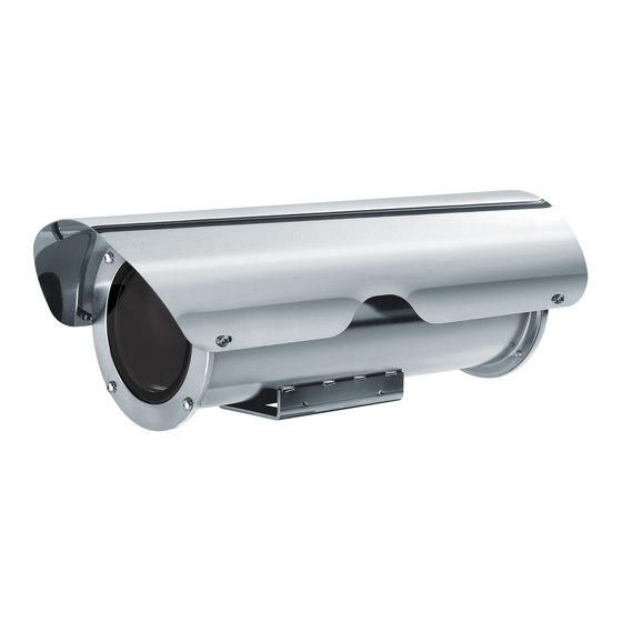
4.1 Product marking label type designation Before proceeding further with installation, make sure the material supplied The NXM36 housing was designed for installation corresponds to the order specification by in highly corrosive environments such as chemical, examining the marking labels. -
Page 8: Model Identification
4.2 Model identification NXM36 - MODEL IDENTIFICATION Model Number Sunshield Heater 120Vac/2 Heater 12Vdc/2 Double heating Power supply 30Vac 4Vac 120Vac/230Vac Hi-PoE NXM36D0000 – – – – – NXM36K0000 – – – – NXM36D1000 – – – – NXM36K1000 –... -
Page 9: Preparing The Product For Use
5 Preparing the product for 6 Installation Never, under any circumstances, make any changes or connections that are not Any change that is not expressly approved shown in this handbook. Failure to follow by the manufacturer will invalidate the the connection instructions that are given guarantee. -
Page 10: Housing Opening
6.2 Housing opening The power cables must be sized according to the ratio between the supply current and the distance to Unscrew the screws (01) on the rear flange (02) using be covered. the hexagonal wrench (03) provided. Open the housing as described in the relative chapter (6.2 Housing opening, page 10). -
Page 11: 120/230Vac Version
6.3.2 120/230Vac version 6.3.3.1 Power consumption configuration Before powering the device, you must set the Nominal section of the cables used: from maximum power consumption of the housing 0.2mm² (24AWG) up to 2.5mm² (13AWG). operating on dip switch SW1. When the power supply voltage is 120/230Vac the circuit will be connected by the terminals shown. -
Page 12: Operating Status
6.4 Housing closure 6.3.3.2 Operating status The LEDs shown in the figure allow to check the Before closing the housing reinsert the bottom product's operating status. orientating the slide according to the installation required, for the right camera fitting (6.1 Installation mode, page 9). -
Page 13: Switching On
For further details on configuration and use, refer to the manual of the relevant Whenever replacing the parts as indicated, accessory or support. always use VIDEOTEC original spare parts and meticulously follow the maintenance instructions supplied with every spare parts kit. -
Page 14: Cleaning
10 Cleaning 11 Information on disposal and recycling Frequency will depend on the type of environment in which the product is used. The European Directive 2012/19/EU on Waste Electrical and Electronic Equipment (WEEE) mandates 10.1 Cleaning the glass window that these devices should not be disposed of in the normal flow of municipal solid waste, but they should Avoid ethyl alcohol, solvents, hydrogenated be collected separately in order to optimize the... -
Page 15: Technical Data
12 Technical data 12.1.3 Electrical Standard version 12.1 NXM36 Supply voltage/Current consumption (version with heater, Ton 15°C±3°C (59°F ±5°F), Toff 22°C±3°C 12.1.1 General (72°F±5°F)): Housing manufactured in polished stainless steel • 12Vdc, 1.6A max (austenitic stainless alloy steel resistant to corrosion •... -
Page 16: Environment
12.2 NTM36 12.1.4 Environment For indoors and outdoors installation 12.2.1 General Submersible: up to -40m (-130ft) (pressure: 4bar) Housing manufactured in polished stainless steel Operating temperature (standard version, with (austenitic stainless alloy steel resistant to corrosion heater): from -20°C (-4°F) up to +60°C (140°F) and heat): Operating temperature (with double heater): from •... -
Page 17: Windows For Camera
12.2.3 Windows for camera 12.2.5 Environment Germanium window: For indoors and outdoors installation • Usable diameter: 55mm (2.1in) Submersible: up to -40m (-130ft) (pressure: 4bar) • Thick: 2mm (0.08in) Operating temperature (standard version, with heater): from -20°C (-4°F) up to +60°C (140°F) •... - Page 18 13 Technical drawings The indicated measurements are expressed in millimetres. Ø 97 POWER SUPPLY USABLE USABLE USABLE AREA AREA AREA B - B A - A C - C VERSION WITH DOUBLE HEATER BOARD FIXING BASE Fig. 11 NXM36. MNVCNXM36_2222_EN...
- Page 19 Ø 97 USABLE USABLE AREA AREA B - B A - A HI-POE BOARD FIXING BASE Fig. 12 NXM36 Hi-PoE. MNVCNXM36_2222_EN...
- Page 20 USABLE AREA AREA B - B A - A BOARD FIXING BASE Fig. 13 NTM36. Headquarters Italy Videotec s.r.l. Via Friuli, 6 - I-36015 Schio (VI) - Italy Tel. +39 0445 697411 - Fax +39 0445 697414 Email: info@videotec.com www.videotec.com MNVCNXM36_2222_EN...
Need help?
Do you have a question about the NXM36 and is the answer not in the manual?
Questions and answers