
Related Manuals for Druck PTC200


Summary of Contents for Druck PTC200
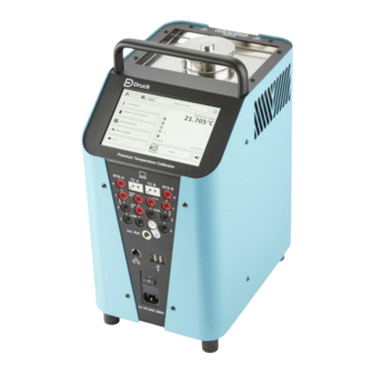
- Page 1 PTC200 PTC700 PTC165(i) PTC255(i) Premium Temperature Calibrators Instruction Manual Druck.com...
- Page 3 This manual contains operating instructions for PTC Series temperature calibrators with software version 28. Technical Advice For technical advice contact Druck or subsidiary manufacturer of this product. A qualified technician must have the necessary technical knowledge, documentation, special test equipment and tools to carry out the required work on this equipment.
- Page 4 This symbol warns the user of the danger of electric shock. This symbol warns the user of the danger of hot surfaces. Druck is an active participant in the UK and EU Waste Electrical and Electronic Equipment (WEEE) take-back initiative (UK SI 2013/3113, EU directive 2012/19/EU).
- Page 5 Abbreviations The following abbreviations are used in this manual; the abbreviations are the same in the singular and plural. Abbreviation Description Ampere Alternating Current Centimetre Centistokes Direct Current Device Under Test e.g. For example etc. And so on Full Scale Ground Hour i.e.
- Page 6 Copyright 2022 Baker Hughes Company. iv | PTC Temperature Calibrators–English...
-
Page 7: Table Of Contents
Contents Description Models Unpacking Intended Purpose Safety Instructions Qualified Personnel General Safety Instructions Special Safety Instructions Calibration Liquid Safety Instructions Construction and Function Construction 3.1.1 Integrated Measurement Instrument Function 3.2.1 Operation Procedure Test Tasks Commissioning and Operation Operating Conditions Electrical Connection 4.2.1 Electrical Connection Procedure Calibrator Preparation... - Page 8 Safety Precautions 12. Decommissioning and Disposal 12.1 Before Decommissioning 12.2 Decommissioning 12.3 Disposal of Calibration Liquid 12.4 Disposal of Calibrator 13. Specification 13.1 Shared Specification 13.2 PTC200 Specification 13.3 PTC700 Specification Copyright 2022 Baker Hughes Company. vi | PTC Temperature Calibrators–English...
- Page 9 13.4 PTC165(i) Specification 13.5 PTC255(i) Specification 13.6 Integrated Measuring Instrument 13.7 Heating and Cooling Times 13.7.1 PTC200 13.7.2 PTC700 13.7.3 PTC165(i) 13.7.4 PTC255(i) Copyright 2022 Baker Hughes Company. English–PTC Temperature Calibrators | vii...
- Page 10 Copyright 2022 Baker Hughes Company. viii | PTC Temperature Calibrators–English...
-
Page 11: Description
The portable instruments are of compact and robust construction so can be used on-site or in a laboratory. The PTC Series may be used for service purposes, or industrial and laboratory applications. 1.1 Models PTC200 PTC700 PTC165 PTC255i Integrated Measuring... -
Page 12: Intended Purpose
Check the completeness of the delivery based on the delivery note. Table 1: Delivery Checklist PTC200 PTC165 PTC165i Item PTC700 PTC255 PTC255i Druck Premium Temperature Calibrator External reference sensor. Dry block insert. ... -
Page 13: Qualified Personnel
In order to guarantee that the calibrator operates safely, the operator must act competently and be conscious of safety issues. Druck provides support for the use of its products either personally or via relevant literature. The customer verifies that our product is fit for purpose based on our technical information. The customer performs customer-specific and application-specific tests to ensure that the product is suitable for the intended use. -
Page 14: Calibration Liquid Safety Instructions
Only use calibration liquids that are suitable for the required temperature range, and which are not flammable. Calibrators are set for specific fluid types. Use only the optional Druck supplied or recommended silicone oil. These oils have temperature limitations that must be adhered to. -
Page 15: Construction And Function
During operation, cooling air is drawn in from the base of the unit (11, 12) and expelled through grilles (6, 8). PTC200 and PTC700 expel air through the top of the unit (6). PTC165(i) and PTC255(i) expel air through side grilles (8). -
Page 16: Integrated Measurement Instrument
3.1.1 Integrated Measurement Instrument The PTC165i and PTC255i are equipped with an integrated measurement instrument. Figure 2: Integrated Measurement Instrument Symbol Description Resistance thermometers (2, 3 or 4-wire) RTD A / B Switch test (socket 1 and 2) TC A / B Thermocouple input. -
Page 17: Function
Figure 3: Insert Overview Table 3 details the required insert diameter and material for each calibrator model. Use only Druck supplied inserts. Druck inserts have the correct tolerances and materials for the calibrator models. Table 3: Insert Diameter and Material... -
Page 18: Operation Procedure
See Table 6. Table 5: Insert Compatibility Insert Reference Sensor PTC200 PTC700 PTC165(i) PTC255(i) Internal Adaptor Sleeve External Air Shield External ... -
Page 19: Test Tasks
The protected test tasks can be neither be deleted nor edited. They serve as templates for your own self-defined test tasks. They can be copied and then modified. This task must not be completed without specific training from Druck. You can define your own test tasks for different DUT or test sequences. These test tasks are directly saved in the calibrator and can be easily activated. -
Page 20: Operating Conditions
Ensure that the calibrator is always connected to a protective earth. Always use a known good mains cable with an appropriate power plug. Use only a Druck specified mains cable. Ensure that the mains outlet is adequately rated and has a protective earth connection. -
Page 21: Calibrator Preparation
Adaptor sleeves with single or multiple holes are used for the calibration of straight temperature sensors. For adaptor sleeve insert compatibility, see Section 3.2 on page 7. 1 Brass adaptor sleeves for PTC200. Aluminum bronze alloy adaptor sleeves for PTC700. 2 Aluminum adaptor sleeves for PTC165(i) and PTC255(i). -
Page 22: Air Shield Insert
4.3.1.1 Installation INFORMATION Use only Druck adaptor sleeves. If in doubt, contact Druck. The adaptor sleeve is inserted into the dry block using the insert exchange tool, see Figure 4 item 3. 4.3.1.2 External Reference Sensor Align the adapter sleeve so that the hole for the external reference sensor is located at 12 o’clock. -
Page 23: Infrared Insert
4.3.3 Infrared Insert The infrared insert is used for contact-less measurement infrared thermometers. The infrared insert has a specially designed surface and surface coating on the inside. As a result, an emissivity of 0.9994 (black body) is achieved. 1 Infrared insert. 2 External sensor bore holes: 2 ×... -
Page 24: Surface Insert
4.3.4 Surface Insert The surface insert is used for calibrating surface temperature sensors. The surface insert is hollow in construction. When installed, the top portion of the surface insert protrudes above the dry block. 1 Surface insert. 2 External sensor bore holes: 1 ×... -
Page 25: Tub Insert
4.3.5 Tub Insert WARNING Wear safety goggles. Calibration liquid may be ejected when working with the tub insert. Always wear safety goggles when handling calibration liquids. INFORMATION Direct filling of the PTC with liquid is not supported. Use a tub insert to contain the calibration liquid. The tub insert is a removable calibration liquid container. - Page 26 4.3.5.2 Sensor Cage and Magnetic Stirrer The sensor cage protects the magnetic stirrer. It prevents the DUT from stopping the magnetic stirrer from rotating. 1 Sensor cage. 2 Magnetic stirrer. Figure 10: Sensor Cage and Magnetic Stirrer The magnetic stirrer ensures a uniform temperature distribution in the calibration liquid. The user interface on the touch screen can be used to control the speed of the magnetic stirrer.
- Page 27 • Always ensure adequate ventilation when working with silicone oil. Hazardous substances may be released. • Spilled or leaked silicone oil results in an extreme danger of slipping. Always clean up spills. • Silicone oil is hygroscopic. Use the work cover to seal the micro bath after use. Alternatively, remove the tub insert from the calibrator and use the transport cover to seal the tub insert.
- Page 28 The maximum fill levels are shown below: 1 Tub insert. 2 Sensor cage. 3 Tub insert transport cover. 4 Magnetic stirrer. Figure 12: Maximum Fill Level Parameter Maximum Fill Level (h) 136 mm (5.35″) Fill Volume ~0.32 liters (10.82 fl oz) Note: The maximum fill level line for the tub insert is below the sleeve exchange tool fixture.
-
Page 29: Integrated Measuring Instrument
If the DUT cable has no cable screen and the measurement result is affected by electromagnetic interference, Druck recommends using a clamp-on ferrite. Insert the DUT cable into the clamp- on ferrite. It is recommended to wrap the DUT cable with multiple turns around the clamp-on ferrite. -
Page 30: Switching On, Cool Down And Switching Off
Turn on the mains switch. The fan of the calibrator starts and the Druck logo appears on the screen. The type designation and the current software version are displayed. The main window is displayed and the calibrator is ready for operation. -
Page 31: Cooling Down The Calibrator
The first entry in the selection list, with its parameters, is displayed as the test task. 4.4.2 Cooling Down the Calibrator HOT SURFACE The calibrator may become very hot when in operation. Touching hot parts can result in serious injuries. Never touch the dry block, micro bath, inserts or the DUT at temperatures above 35 °C (95 °F) or below 10 °C (50 °F). -
Page 32: User Interface
5. User Interface 5.1 Main Window Figure 15: Main Window Function Description Tap the icon to open the “Calibrator Setup” window. The Calibrator Setup calibrator settings can be change. See Section 7. Tap the icon to open the “Select Log Data” window. Saved Measurement Logs measurement logs can be selected and viewed. -
Page 33: Display Range
5.2 Display Range Figure 16: Display Range Window Icon Group Icon Description Status of reference sensor and DUT. Status Heating Cooling Controller Stable with standard deviation. Controller off. Internal reference sensor. Reference Sensor External reference sensor. Micro bath: (Not supported on PTC Series calibrators) Tub insert Dry block... -
Page 34: Toolbar
Icon Group Icon Description Data acquisition disabled. User input data acquisition. Data Acquisition Automatic data acquisition. Step/Cycle Operating Mode Switch test. 5.3 Toolbar The following icons are used: Icon Name Description Return to the previous window. Changes are discarded without Cancel / back saving. -
Page 35: Test Task
Use the web browser to log onto the WebApp. The WebApp requires no additional software to be installed on the computer or smartphone. Refer to Druck document 176M3205 for full WebApp instructions. The document can be downloaded from the following link: https://druck.com... -
Page 36: Select Test Task
6.1 Select Test Task Select a test task and confirm your selection. Figure 18: Select Test Task Window 6.2 Configure Test Task Select the desired test task and tap the icon. Figure 19: Select Test Task Window Note: Protected test tasks cannot be edited. Make a copy of the test task first. Create a new test task or edit an unprotected test task. -
Page 37: Name Of Test Task
Configure the test task with the required parameters. Figure 20: Configure Test Task Window 6.2.1 Name of Test Task In the “Configure Test Task” window, see Figure 20, tap the “Name” icon. Enter the new name of the test task and confirm the input. 6.2.2 Data Acquisition In the “Configure Test Task”... - Page 38 6.2.3.1 Link Function to Test Task Select the desired function and confirm the selection with the icon. Figure 21: Link Function to Test Task 6.2.3.2 Configure the Function Select the desired function and tap the icon. Figure 22: Select Function Window Note: Protected test tasks cannot be edited.
-
Page 39: Device Under Test (Dut)
Stability Range The stability range defines the maximum deviation from the set point which the calibrator should detect as stable. The smallest permitted value is 0.001. 6.2.4 Device Under Test (DUT) In the “Configure Test Task” window, see Figure 20, tap the “DUT” icon. -
Page 40: Test Points
Confirm the selection. Waiting Time The waiting time is a manually entered time delay to allow the DUT to stabilize before data acquisition. Note: The waiting time is only used if user input was selected for data acquisition. Gradient The gradient is used when the internal measuring instrument or TTScan is selected for data acquisition. - Page 41 Change temperature and dwell time and confirm the new values. 6.2.5.3 Test Point Calculation Use Test Point Calculation to automatically calculate the intervening test points between a specified first and last test point. Note: When a parameter is changed, the other dependent parameters are automatically recalculated.
- Page 42 The screen returns to the previous window. Defining the Number of Steps Note: The total number of resulting test points is always one higher than the entered number of steps. Tap the field “Number of Steps” to change the number of steps. Enter the new value and confirm the input.
-
Page 43: Alarm Settings
6.2.6 Alarm Settings Use the alarm settings to configure how and when the calibrator activates the alarm signal. In the “Configure Test Task” window, see Figure 20, tap the “Alarm Settings” icon. Figure 27: Alarm Settings Window Select the desired entries from the list. Confirm the selection. -
Page 44: Configure Network
7.2 Update Calibrator Software Note: The calibrator software version is displayed in menu: Calibrator Setup >> System Information Download the latest calibrator software from: https://druck.com/software Unpack the downloaded ZIP archive. Save the file “update.tar” in the root directory of the USB flash drive. -
Page 45: Configure Presentation Format
7.3 Configure Presentation Format In the “Calibrator Setup” window, see Figure 29, tap the “Presentation Format” icon. Figure 30: Presentation Format Configuration Window The following configuration options for dialog boxes, the configuration toolbar and access level are available. Dialogbox DELETE Configure whether a warning message is displayed before an item is deleted. -
Page 46: Starting The Testing
The calibrator has a suitable installation site and operational position. See Section 4.1. The electrical connections have been made correctly. See Section 4.2. The correct insert has been selected for the testing. See Section 4.3. The insert is clean and dry. Note: Ice and condensation can be removed from the insert by gently heating above 100 °C (212 °F). -
Page 47: After The Testing
The test task is aborted. The calibrator goes to the “Test End” temperature defined by the test task. See “Behavior at Test End” on page 32. Note: Do not leave the calibrator unattended at high temperatures. See Section 4.4.2. Wait until the calibrator has cooled down sufficiently. 8.4 After the Testing Allow the calibrator to cool to room temperature. -
Page 48: Troubleshooting
The calibrator is maintenance-free and cannot be repaired by the user. In case of a defect, the calibrator must be returned to Druck, or approved service representative for repair. For safe operation of the calibrator, the following checks must be carried out at regular intervals. -
Page 49: Annually
Have a trained technical person carry out an electrical safety inspection. 11.1.3 Recalibration It is recommended to send the calibrator to Druck for recalibration after 36 months, or after a maximum of 500 operating hours, whichever is sooner. 11.1.4 Calibration Liquid Calibration liquids become contaminated with age and with use. -
Page 50: Adjustment
Ensure that your cleaning agent cannot be a source of danger from a reaction with parts of the calibrator or the materials inside. If unsure of clean agent compatibility, contact Druck Services. 11.3.2 Vent Grilles for Inlet Air... -
Page 51: Return Goods/Material Procedure
Service by unauthorized sources will affect the warranty and may not guarantee further performance. You must inform Druck if the product has been in contact with any hazardous or toxic substance. The relevant COSHH or in the USA, MSDS, references and precautions to be taken when handling. -
Page 52: Disposal Of Calibration Liquid
Dispose of the calibration liquid in accordance with the Technical Safety Data Sheet. 12.4 Disposal of Calibrator See “Marks and Symbols on the Equipment” on page ii for details of the Druck WEEE take-back scheme. 13. Specification 13.1 Shared Specification... -
Page 53: Ptc200 Specification
13.2 PTC200 Specification Specification PTC200 -55 °C to 200 °C (-67°F to 392 °F) Temperature range Setting range -60 °C to 200 °C (-76°F to 392 °F) External Reference Sensor Internal Reference Sensor Control sensor (switchable) Dry Block: Display accuracy ±... -
Page 54: Ptc700 Specification
13.3 PTC700 Specification Specification PTC700 to 700 °C (T to 1292 °F) Temperature range Setting range 0 °C to 700 °C (32°F to 1292 °F) External Reference Sensor Internal Reference Sensor Control sensor (switchable) Air Shield: Display accuracy ± 0.27 °C (± 0.486 °F) Temperature stability ±... - Page 55 Specification PTC700 - Height + Handle 330+50 mm (13.0+2.0″) - Depth 300 mm (11.8″) - Weight ~ 10 kg (~ 22.1 lbs) The PTC700 can be operated up to 700 °C (1292 °F). It achieves optimum accuracy up to 660 °C (1220 °F). All values measured at 660 °C (1220 °F).
- Page 56 13.4 PTC165(i) Specification Specification PTC165(i) External Reference Sensor Internal Reference Sensor Control sensor (switchable) Air Shield (DB): -30 °C to 160 °C (-22 °F to 320 °F) Temperature range Display accuracy ± 0.07 °C (± 0.126 °F) Temperature stability ± < 0.001 to 0.005 °C (±...
- Page 57 Specification PTC165(i) Power supply 100…240 V ac, 50/60 Hz Power consumption Approx. 375 W Fuse 2 off 5 × 20 mm T6.3H250V Case: Dimensions - Width 210 mm (8.27″) - Height + Handle 380+50 mm (15.0+2.0″) - Depth 300 mm (11.8″) - Weight ~ 13 kg (~ 28.7 lbs) At an ambient temperature of 20 °C (68 °F).
- Page 58 13.5 PTC255(i) Specification Specification PTC255(i) Temperature range to 255 °C (T to 491 °F) Setting range 0 °C to 255 °C (32°F to 491 °F) Hysteresis ± 0.010 °C (± 0.018 °F) Control sensor (switchable) External Reference Sensor Internal Reference Sensor Air Shield (DB): Display accuracy ±...
- Page 59 Specification PTC255(i) - Width 210 mm (8.27″) - Height + Handle 330+50 mm (13.0+2.0″) - Depth 300 mm (11.8″) - Weight ~ 8.5 kg (~ 18.7 lbs) Silicone oil 50 cSt, see Section 2.4. 13.6 Integrated Measuring Instrument Note: Only applicable to models PTC165i and PTC255i. Specification Integrated Measuring Instrument Resistance Thermometer:...
- Page 60 The following times are guide values only. They are measured at a room temperature of 23 °C (73.4 °F) and do not include transient effects. 13.7.1 PTC200 -100 Time (minutes) Figure 36: PTC200 Heating and Cooling Times Copyright 2022 Baker Hughes Company. 50 | PTC Temperature Calibrators–English...
- Page 61 13.7.2 PTC700 Time (minutes) Figure 37: PTC700 Heating and Cooling Times 13.7.3 PTC165(i) 13.7.3.1 Dry Block, Infrared and Surface Inserts Infrared Time (minutes) Surface Dry Block Figure 38: PTC165(i) Heating and Cooling Times Copyright 2022 Baker Hughes Company. English–PTC Temperature Calibrators | 51...
- Page 62 13.7.3.2 Silicone Oil (10 cSt) Time (minutes) Figure 39: PTC165(i) Heating and Cooling Times 13.7.4 PTC255(i) 13.7.4.1 Dry Block, Infrared and Surface Inserts Infrared Time (minutes) Surface Dry Block Figure 40: PTC255(i) Heating and Cooling Times Copyright 2022 Baker Hughes Company. 52 | PTC Temperature Calibrators–English...
- Page 63 13.7.4.2 Silicone Oil (50 cSt) Time (minutes) Figure 41: PTC255(i) Heating and Cooling Times Copyright 2022 Baker Hughes Company. English–PTC Temperature Calibrators | 53...
- Page 64 Copyright 2022 Baker Hughes Company. 54 | PTC Temperature Calibrators–English...
- Page 66 Office Locations https://druck.com/contact Services and Support Locations https://druck.com/service Copyright 2022 Baker Hughes Company. This material contains one or more registered trademarks of Baker Hughes Company and its subsidiaries in one or more countries. All third- party product and company names are trademarks of their respective holders.
Need help?
Do you have a question about the PTC200 and is the answer not in the manual?
Questions and answers