
Subscribe to Our Youtube Channel
Related Manuals for Toro 39514


Summary of Contents for Toro 39514
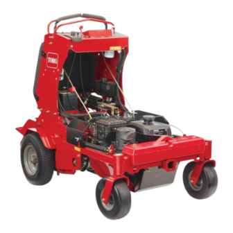
- Page 1 Form No. 3431-971 Rev A 24in Stand-On Aerator Model No. 39514—Serial No. 404324200 and Up *3431-971* A Register at www.Toro.com. Original Instructions (EN)
- Page 2 Whenever you need service, genuine Toro parts, or additional information, contact an Authorized Service Dealer or Toro Customer Service and have the model and serial numbers of your product ready. Figure 1 identifies the location of the model and serial numbers ©...
-
Page 3: Table Of Contents
Contents Checking the Spark Arrester ......36 Electrical System Maintenance ......36 Checking the Safety Interlock ......36 Safety ............... 4 Jump Starting a Discharged Battery....36 Safety Alert Symbol ..........4 Servicing the Battery......... 38 General Safety ........... 4 Drive System Maintenance ........ -
Page 4: Safety
General Safety This machine is capable of amputating hands and feet and of throwing objects. Toro designs and tests this machine to offer reasonably safe service; however, failure to comply with safety instructions may result in injury or death. -
Page 5: Safety And Instructional Decals
Safety and Instructional Decals Safety decals and instructions are easily visible to the operator and are located near any area of potential danger. Replace any decal that is damaged or missing. decal121-6161 121-6161 1. Entanglement hazard, belt—stay away from moving parts; keep all guards in place. - Page 6 decal135-3685 135-3685 1. Read and understand the Operator’s Manual before servicing 6. Grease the belt idler pivot every 100 hours this machine. 2. Clean and oil the chains and check the chain tension twice 7. Check the tire pressure - 23 psi twice every 50 hours every 8 hours 3.
- Page 7 135-2013 STOP decal135-2013-1 135-2013 1. Operator weight adjustment 5. Throttle—slow 9. Parking brake—engage 2. Increase 6. Engine—on 10. Parking brake—release 3. Decrease 7. Engine—start 4. Throttle—fast 8. Engine—off decal135-2014 135-2014 1. Fast 6. Wheels and tines rotate when moving 11. Thrown object hazard—pick up debris backward.
- Page 8 decal135-2016 135-2016 1. Electronic tine depth-decrease 2. Electronic tine depth-increase 3. Press and hold 1 second to turn on—tine ground engagement foot switch unlock 4. Press and hold 1 second to turn off—tine ground engagement foot switch lock decal135-3183 135-3183 1.
-
Page 9: Setup
Setup Loose Parts Use the chart below to verify that all parts have been shipped. Procedure Description Qty. – No parts required Check the battery charge. – No parts required Checking the transmission fluid. – No parts required Check the auxiliary hydraulic fluid level. Media and Additional Parts Description Qty. -
Page 10: Checking The Transmission Fluid
Checking the Transmission Fluid No Parts Required Procedure The transmission is shipped with transmission fluid. Check the transmission fluid level and, if necessary, add fluid to the specified level; refer to Transmission Fluid Specification (page 46) Checking the Transmission Fluid Level (page 46). -
Page 11: Product Overview
Controls Product Overview g232039 Figure 4 1. Platform 4. Motion-control levers 2. Parking brake lever 5. Fuel cap g223341 3. Engine controls Figure 5 1. Tine ground engagement 7. Choke foot switch 8. Right motion-control lever 2. Operator weight adjustment control 3. -
Page 12: Hour Meter/Tine Engagement Display
Note: Important: The lockout feature is engaged each time the The tines rotate when the engine is switched off. motion-control levers are moved out of the position. EUTRAL Operator Weight Adjustment Control The operator weight adjustment valve is located at the left side of the control console (Figure g223330... - Page 13 Use the hour meter/tine engagement display to show the following information generated by the smart controller/electronic depth control system: Aerating Hours Electronic depth Parking brake control setting indicator indicator for the tines Alert and Error Engine Hours Maintenance Messages Reminders and Alerts Battery voltage Interlock status...
-
Page 14: Specifications
Authorized Service Dealer or authorized Toro at the front right side of the engine (Figure 11). distributor or go to www.Toro.com for a list of all approved attachments and accessories. To ensure optimum performance and continued safety certification of the machine, use only genuine Toro replacement parts and accessories. -
Page 15: Before Operation
In certain conditions, fuel is extremely safely perform the job. Only use accessories and flammable and highly explosive. A fire or attachments approved by Toro. explosion from fuel can burn you and others • Inspect the area where the equipment is to be and can damage property. -
Page 16: Performing Daily Maintenance
Fuel Specification • Lubricating the Chains (page 31) • Checking the Engine-Oil Level (page 33) Petroleum Use unleaded gasoline with an octane rating of 87 fuel or higher ((R+M)/2 rating method). • Checking the Safety Interlock (page 36) Use an unleaded-gasoline blend with up to 10% •... -
Page 17: Positioning The Air-Cleaner Cover For Cold Or Warm Air Temperature
Positioning the Air-Cleaner WARNING Cover for Cold or Warm Air Operating engine parts, especially the muffler, become extremely hot. Severe burns can Temperature occur on contact and debris, such as leaves, grass, brush, etc. can catch fire. Important: Running the engine with the air-cleaner cover positioned for cold-weather •... - Page 18 • Keep hands and feet away from moving parts. – Be alert and turn the machine off if children If possible, Do Not make adjustments with the enter the area. engine running. – Before and while backing or changing direction, look behind, down, and side-to-side for small WARNING children.
-
Page 19: Using The Smart Controller/Electronic Depth Control
Using the Smart Controller/Electronic Depth Control Hour Meter/Tine Engagement Display The smart controller/electronic depth control monitors the overall electrical system and displays information in the hour meter/tine engagement display. The controller displays machine hours, interlock status, and maintenance reminders. Screen Icons g222486 The information screen uses the following icons: Figure 14... - Page 20 Information Screens The fourth screen displays the number of hours until the engine oil maintenance is required. The main information screens include: • The Startup Screens • The Default Screen (engine-on) • The Tine Engagement Display • Maintenance Reminders and Alerts •...
- Page 21 Maintenance Reminder Screens • The hour meter displays engine hours when the hour glass symbol is flashing. The hour meter displays the number of engine • The display turns off after 5 minutes after the hours until either the engine oil or transmission oil ignition key is switched to the position.
-
Page 22: Opening And Closing The Fuel Shutoff Valve
Service Transmission Reminder On a cold engine, push the choke lever forward into the O position. On a warm engine, leave The transmission oil maintenance reminder (Figure the choke in the O position. 23) counts down from the initial break-in service Turn ignition switch to the S position. -
Page 23: Locking/Unlocking The Tine Depth Setting
remove a longer plug. Tap the top of the switch to raise the tine depth to remove a shorter plug. Note: The ideal plug depth is 6.4 to 7.6 cm (2.5 to 3 inches). Adjust the controls to adapt to the soil conditions. -
Page 24: Driving The Machine
Engage the parking brake. Remove the key to prevent children or other unauthorized persons from starting the engine. Close the fuel-shutoff valve when you will not use the machine for a few days, when you are transporting the machine, or when the machine is parked inside a building. -
Page 25: Drive-Wheel Release Valves
Releasing Valves to Push the Machine If you must push the machine by hand, you must release the drive-wheel release valves. Engage the parking brake, shut off the engine, remove the key, and allow all the moving parts to stop. Move the lever to the larger opening of the slot (Figure 29). -
Page 26: After Operation
Hauling the Machine Pull the lever upward until the washer is outside of the frame (Figure 29). Use a heavy-duty trailer or truck to transport the Move the release-valve lever back to the narrow machine. Ensure that the trailer or truck has all the portion of the slot, and release the lever (Figure necessary lighting and marking as required by law. - Page 27 WARNING Loading a machine on a trailer or truck increases the possibility of backward tip-over. Backward tip-over could cause serious injury or death. • Use extreme caution when operating a machine on a ramp. • Use only a single, full-width ramp; Do not use individual ramps for each side of the machine.
-
Page 28: Maintenance
Maintenance Download a free copy of the electrical or hydraulic schematic by visiting www.Toro.com and searching for your machine from the Manuals link on the home page. WARNING Maintenance Safety Removal or modification of original Information equipment, parts and/or accessories... - Page 29 WARNING Hydraulic fluid escaping under pressure can penetrate skin and cause injury. Fluid accidentally injected into the skin must be surgically removed within a few hours by a doctor familiar with this form of injury or gangrene may result. – If equipped, make sure all hydraulic fluid hoses and lines are in good condition and all hydraulic connections and fittings are tight before applying...
-
Page 30: Recommended Maintenance Schedule(S)
Recommended Maintenance Schedule(s) Maintenance Service Maintenance Procedure Interval • Change the engine oil. • Check the transmission output shaft nut torque specification. After the first 5 hours • Check transmission mount bolt torque. • Change the auxiliary hydraulic reservoir filter and fluid. After the first 100 hours •... -
Page 31: Pre-Maintenance Procedures
Pre-Maintenance Lubrication Procedures Lubricating the Chains CAUTION Service Interval: Before each use or daily Raising the machine for service or Important: Do not lubricate the chains with maintenance relying solely on mechanical penetrating oil or solvents. Use an oil or chain or hydraulic jacks could be dangerous. -
Page 32: Lubricating The Grease Fittings
Lubricating the Grease Engine Maintenance Fittings Servicing the Air Cleaner Note: See the chart below for service intervals. Service Interval: Every 50 hours—Clean the foam Shut off the engine, wait for all moving parts to pre-cleaner (more frequently in stop, and remove the key. Engage the parking dusty conditions). -
Page 33: Servicing The Engine Oil
Checking the Engine-Oil Level Wipe dirt away from the base and the cover with a moist rag. Service Interval: Before each use or daily Note: Be careful to prevent dirt and debris from Important: Do not operate the engine with the oil entering the air duct leading to the carburetor. - Page 34 Changing the Engine Oil Service Interval: After the first 5 hours Every 100 hours (more often under severe conditions.) Note: Dispose of the used oil at a recycling center. Park the machine so that the drain side is slightly lower than the opposite side to assure the oil drains completely.
-
Page 35: Servicing The Spark Plug
Note: You can exit the Service Engine screen at any time by turning the key to either the OFF or the START positions. Servicing the Spark Plug Service Interval: Every 160 hours g206628 Type for all Engines: NGK BR6HS, Champion Figure 41 RTL86C, or equivalent Air Gap: 0.76 mm (0.030 inch) -
Page 36: Checking The Spark Arrester
If the machine does not pass either of the tests Fire may result in personal injury or property that follow, Do not operate the machine. Contact your authorized Toro distributor. damage. Do not refuel or run engine unless a spark Checking the Engine Starting arrester is installed. - Page 37 Choose jumper cables with color coded or DANGER polarity labeled cables or clamps. Jump starting a weak battery that is cracked, frozen, has low electrolyte level, or an Connecting the Jumper Cables open/shorted battery cell, can cause an explosion resulting in serious personal injury. CAUTION Do not jump start a weak battery if these Connecting the jumper cables incorrectly...
-
Page 38: Servicing The Battery
Starting the Engine and Removing Allowing batteries to stand for an extended period of time without recharging them results in reduced the Jumper Cables performance and service life. To preserve optimum Start the engine. battery performance and life, charge batteries in storage when the open circuit voltage drops to 12.4 V. -
Page 39: Drive System Maintenance
Drive System Remove the screw, washer, and ground cable from the engine. Connect the negative battery Maintenance cable. Note: If time does not permit charging the battery or if charging equipment is not available, Checking the Drive Tire Air connect the negative battery cables and run the vehicle continuously for 20 to 30 minutes to Pressure charge the battery. -
Page 40: Checking The Condition Of The Chains
Checking the Condition of the Chains Service Interval: Before each use or daily Shut off the engine, engage the parking brake, wait for all moving parts to stop, and remove the key. Check the chains on both sides of the machine for proper tension. -
Page 41: Adjusting The Motion Control Linkage
Adjusting the Motion Adjusting the Motion Control Linkage Control Tracking Refer to Preparing for Maintenance (page 31). If the machine travels or pulls to one side when the motion control levers are in the full forward position, Push the control levers all the way forward to the adjust the tracking. -
Page 42: Check Transmission Mount Bolt Torque
Check Transmission Mount Brake Maintenance Bolt Torque Adjusting the Parking Service Interval: After the first 5 hours Brake Yearly thereafter Torque the 4 transmission bolts to 56-69 N-m (41-51 If the parking brake does not hold securely, an ft-lb); refer to Figure adjustment is required. -
Page 43: Belt Maintenance
Belt Maintenance Checking the Condition and Tension of the Belts Service Interval: Every 50 hours Shut off the engine, engage the parking brake, wait for all moving parts to stop, and remove the key. Check the auxiliary pump drive belt condition and tension;... -
Page 44: Hydraulic System Maintenance
Hydraulic System Maintenance Auxiliary Hydraulic Fluid Specification Hydraulic fluid type: AW-32 hydro fluid g266183 Checking the Auxiliary Hydraulic Fluid Level Note: The machine is shipped with hydraulic fluid in the reservoir. Run the machine for approximately 15 minutes to purge any extra air out of the hydraulic system. - Page 45 Shut off the engine, engage the parking brake, wait for all moving parts to stop, and remove the key. Allow the engine to cool. Carefully clean the area around the front of the auxiliary pump and fill cap; also clean around the filter.
-
Page 46: Transmission Fluid Specification
Transmission Fluid Changing the Hydraulic Specification Transmission Filters and Fluid Transmission fluid type: Toro® Hypr-Oil™ 500 or Mobil® 1 15W-50 synthetic motor oil. Service Interval: After the first 100 hours Important: Use the specified fluid. Other fluids Every 250 hours thereafter could cause system damage. - Page 47 Installing the Transmission Filters WARNING Apply a thin coat of the specified hydraulic fluid The engine must be running and the drive to the rubber seal of the new filters; refer to wheels must be turning so motion control Transmission Fluid Specification (page 46).
-
Page 48: Tine Maintenance
Tine Maintenance The transmission-oil maintenance reminder resets to 250 (hours), exits the service transmission screen, and returns to the default Checking the Tines screen. Note: You can exit the service transmission screen Service Interval: Before each use or daily at any time by turning the key to either the OFF or Shut off the engine, engage the parking brake, the START positions. -
Page 49: Adjusting The Tine Drive Chain
Adjusting the Return-to-Up Secure the cover panel to the chassis with the 2 thumbscrews and 2 washers (Figure 59) that Spring you removed in step 3, and torque the bolts to 37 to 45 N∙m (27 to 33 in-lb) WARNING Adjusting the Tine Drive Springs have stored energy. -
Page 50: Chassis Maintenance
Chassis Maintenance Cleaning Washing the Machine Check for Loose Hardware Wash the machine as needed using water alone Service Interval: Before each use or daily or with a mild detergent. You may use a rag when Stop engine, wait for all moving parts to stop, washing the machine. -
Page 51: Cleaning The Debris From The Machine
Remove cooling shrouds from engine. for batteries must follow relevant federal, state, or local laws. Clean cooling fins of the engine. If a battery is being replaced or if the machine Note: Also clean dust, dirt, and oil from external containing the battery is no longer operating and is surfaces of engine, which can cause improper being scrapped, remove the battery and take it to a... -
Page 52: Storage
Check and tighten all bolts, nuts, and screws. Repair or replace any part that is damaged. Paint all scratched or bare metal surfaces. Paint is available from your authorized Toro distributor. Store the machine in a clean, dry garage or storage area. -
Page 53: Troubleshooting
Troubleshooting Alert and Error Messages Message Icon Description Resolution Voltage Error The ignition key is in the Check the battery, charging position and the smart system, and wiring. controller/electronic depth control measures that the electrical system is less than 12.3V or greater than 16V. The voltage error icon displays, and the LED status light flashes a red. - Page 54 Problem Possible Cause Corrective Action The engine does not start, starts hard, or 1. The fuel tank is empty. 1. Fill the fuel tank. fails to keep running. 2. The fuel-shutoff valve is closed. 2. Open the fuel-shutoff valve. 3. The throttle and choke are not in the 3.
- Page 55 Problem Possible Cause Corrective Action The tines do not raise. 1. There is a short in the wire harness. 1. Contact an Authorized Service Dealer. 2. The return-to-up springs are not 2. Adjust the return-to-up springs. properly adjusted. 3. The return-to-up springs are damaged. 3.
-
Page 56: Schematics
Schematics B+ START g231578 Electrical Schematic (Rev. 126-5344 rev A) - Page 57 g243786 Hydraulic Schematic (Rev. A)
- Page 58 Notes:...
- Page 59 While the exposure from Toro products may be negligible or well within the “no significant risk” range, out of an abundance of caution, Toro has elected to provide the Prop 65 warnings. Moreover, if Toro does not provide these warnings, it could be sued by the State of California or by private parties seeking to enforce Prop 65 and subject to substantial penalties.
Need help?
Do you have a question about the 39514 and is the answer not in the manual?
Questions and answers