
Related Manuals for Toro 39519


Summary of Contents for Toro 39519
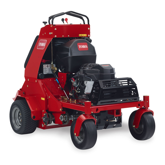
- Page 1 Form No. 3412-564 Rev B 30in Stand-On Aerator Model No. 39519—Serial No. 400000000 and Up *3412-564* B Register at www.Toro.com. Original Instructions (EN)
- Page 2 California Public Resource Code Section 4442 to additional information, contact an Authorized Service use or operate the engine on any forest-covered, Dealer or Toro Customer Service and have the model brush-covered, or grass-covered land. Other and serial numbers of your product ready.
-
Page 3: Table Of Contents
Contents Belt Maintenance ..........43 Checking the Condition and Tension of the Belts.............. 43 Safety ............... 4 Adjusting the Auxiliary Pump Drive Safe Operating Practices........4 Belt..............43 Aerator Safety ............ 6 Replacing the Transmission-Drive Belt ..... 43 Slope Indicator ........... 7 Controls System Maintenance ...... -
Page 4: Safety
The owner is responsible for training the users. to the original equipment or failure to use • Never let children or untrained people operate or original Toro parts could lead to serious service the equipment. injury or death. Unauthorized changes to the Note:... - Page 5 Note: • Reduced footing could cause slipping. Do not fill containers inside a vehicle, on a truck, or on a trailer bed with a plastic liner. Always place • Slow down and use extra care on hillsides. Be containers on the ground away from your vehicle sure to travel side to side on hillsides.
-
Page 6: Aerator Safety
The following list contains safety information specific • Follow the manufacturer’s recommendations for to Toro products and other safety information you wheel weights or counter weights to improve must know. stability. •... -
Page 7: Slope Indicator
Slope Indicator g011841 Figure 3 This page may be copied for personal use. 1. The maximum slope you can safely operate the machine on is 15 degrees. Use the slope chart to determine the degree of slope of hills before operating. Do not operate this machine on a slope greater than 15 degrees. Fold along the appropriate line to match the recommended slope. -
Page 8: Safety And Instructional Decals
Safety and Instructional Decals Safety decals and instructions are easily visible to the operator and are located near any area of potential danger. Replace any decal that is damaged or missing. decal93-6686 93-6686 1. Hydraulic fluid 2. Read the Operator's Manual. - Page 9 decal126-2054 126-2054 1. Wheel lug nut torque 129 N∙m (95 ft-lb) (4x) 2. Wheel hub nut torque 319 N∙m (235 ft-lb) 3. Read and understand the Operator’s Manual before performing any maintenance; check the torque every 100 hours. decal121-6163 121-6163 1.
- Page 10 decal126-4528 126-4528 1. Rotate counterclockwise to decrease pressure 5. Parking brake - release 2. Rotate clockwise to increase pressure 6. Parking brake - engage 3. On - tine ground engagement foot switch 7. Cutting/dismemberment hazard of hand or foot, tines–stay away from moving parts;...
- Page 11 decal116-9392 116–9392 1. Read the instructions before servicing or performing maintenance; read the Operator’s Manual for information on lubricating the machine.
-
Page 12: Setup
Setup Media and Additional Parts Description Qty. Operator's Manual Read before operating the machine. Start the machine. Checking Tire Pressure Servicing the Battery No Parts Required No Parts Required Procedure Procedure Check the tire pressure in the drive tires. Note: The machine is shipped with a filled, lead-acid battery. -
Page 13: Checking Fluid Levels
Turn the key in the ignition switch to the O position and remove the key. Measure the voltage of the battery with a voltmeter. Use the table below to locate the charge state or the battery, and if needed, the battery-charger setting and charging interval recommended to charge the battery to 12.6 V or greater. -
Page 14: Removing The Cylinder Stop
Removing the Cylinder Stop No Parts Required Procedure Note: Raise the tines before removing the cylinder stop. Running the engine charges the hydraulic system and raises the tines. Add a small amount of fuel to the fuel tank; refer g020266 Figure 5 Adding Fuel (page 19). -
Page 15: Product Overview
Product Overview g025895 Figure 7 1. Left traction-control lever 5. Reverse 2. Right traction-control lever 6. Front of the machine 7. Neutral 3. Front reference bar 4. Forward g020220 Figure 6 Tine-Pressure Control 1. Platform 4. Engine controls The tine-pressure control is located on the left side of 2. - Page 16 Choke Lever The choke lever (Figure 8) is located on the control console (black lever). The choke lever is used to aid in starting a cold engine. To set the choke to the O position, move the choke lever forward. To reduce the choke, move the choke lever backward.
- Page 17 On/Off Tine Ground Engagement Foot Switch Located above the tine down pressure control on the control console. To enable the tines ground engagement, push down on the top of the switch. To disable the tines ground engagement, push down on the rear of the switch. Tine-Pressure Gauge The tine-pressure gauge is located in the middle of the control console...
-
Page 18: Specifications
Operation Disengage the parking brake to allow you to push the machine by hand. Important: Do not tow the machine. Note: Determine the left and right sides of the machine from the normal operating position. To reset the drive system back to the operating position, move the lever to the larger opening of the slot, push inward until the washer is inside the frame, Checking the Engine-Oil... -
Page 19: Adding Fuel
Adding Fuel Fuel tank capacity: 18.9 L (5 US Gallons) • For best results, use only clean, fresh (less than 30 days old), unleaded gasoline with an octane rating of 87 or higher ((R+M)/2 rating method). • ETHANOL: Gasoline with up to 10% ethanol g025899 (gasohol) or 15% MTBE (methyl tertiary butyl ether) by volume is acceptable. -
Page 20: Lubricating The Chains
Add the correct amount of fuel stabilizer/conditioner DANGER to the fuel. In certain conditions during fueling, static Note: A fuel stabilizer/conditioner is most electricity can be released causing a spark effective when mixed with fresh fuel. To minimize which can ignite the fuel vapors. A fire or the chance of varnish deposits in the fuel system, explosion from fuel can burn you and others use fuel stabilizer at all times. - Page 21 Turn the key in the ignition switch to the O position, engage the parking brake, wait for all moving parts to stop, and remove key. Raise the machine and support it with jack stands with a 460 kg (1,015 lb) capacity. CAUTION Raising the machine for service or maintenance relying solely on...
-
Page 22: Checking The Safety-Interlock System
Ignition Switch (page 16). Note: If the machine does not pass this test, do not operate. Contact your authorized Toro Service Dealer. Important: It is essential that the operator safety mechanisms be connected and in proper operating condition prior to use for aerating. - Page 23 Starting the Engine Stand on the switch and move the traction-control levers forward to aerate (Figure 16); refer to Move the traction-control levers to the N EUTRAL Traction-Control Levers (page 15). position and engage the parking brake; refer Adjust the throttle for the working conditions; Traction-Control Levers (page 15) refer to Throttle Lever (page...
- Page 24 Stopping the Engine Move the traction-control levers to the N EUTRAL position and bring the machine to a full stop; refer to Traction-Control Levers (page 15). Lift your foot off of the tine ground engagement foot switch control to raise the tines; refer to Raising the Tines (page 23).
-
Page 25: Transporting The Machine
The machine moves faster the farther you move CAUTION the traction-control levers from the neutral This machine does not have proper turn position. signals, lights, reflective markings, or a To stop, position both traction-control levers in slow moving vehicle emblem. Driving on a the neutral operate position. -
Page 26: Loading The Machine
Loading the Machine Use extreme caution when loading units onto trailers or trucks. Use 1 full-width ramp that is wide enough to extend beyond the rear tires is recommended instead of individual ramps for each side of the machine (Figure 22). -
Page 27: Maintenance
Maintenance WARNING WARNING While you are maintaining or adjusting the The engine can become very hot. Touching a machine, someone could start the engine. hot engine can cause severe burns. Accidentally starting the engine could Allow the engine to cool completely before seriously injure you or other bystanders. -
Page 28: Pre-Maintenance Procedures
Maintenance Service Maintenance Procedure Interval • Replace the primary air cleaner element — check secondary air cleaner element; replace if dirty. (May need more often under severe conditions. See the Engine Owner’s Manual for additional information.) • Clean the foam air-cleaner element (more often under severe conditions). Every 250 hours •... -
Page 29: Lubrication
Installing the Console Pad Lubrication Align the 4 flanged-head bolts at the forward face of the console pad to the 4 keyhole slots in Lubricating the Grease the frame of the console (Figure 23). Fittings Move the pad forward until the pad is flush to the console frame (Figure 23). -
Page 30: Lubricating The Casters
Removing the Caster-Wheel Assembly Connect a grease gun to the fitting (Figure 24). Pump grease into the fittings until grease begins Turn the key in the ignition switch to the O to ooze out of the bearings. position, engage the parking brake, wait for all moving parts to stop, and remove key. - Page 31 mm (1/8 inch) from the outer surface of the spacer nut to the end of the axle inside the nut. Insert the assembled nut and axle into the wheel at the side of the wheel with the new seal and bearing (Figure 27).
-
Page 32: Engine Maintenance
Engine Maintenance Carefully pull the foam element off the paper element (Figure 28). Servicing the Air Cleaner Servicing the Foam Air-Cleaner Element Service Interval: Every 250 hours—Replace the primary air cleaner element — Service Interval: Every 250 hours (more often under check secondary air cleaner severe conditions). -
Page 33: Servicing The Engine Oil
Servicing the Engine Oil Oil Type: Detergent oil (API service SJ or later) Engine Oil Capacity: 1.7 L (1.8 US qt) with the filter removed; 1.5 L (1.6 UD qt) without the filter removed Oil viscosity: Refer to the table below. g004216 Figure 29 Changing the Engine Oil... - Page 34 g025976 g026005 Figure 32 Start the engine and drive to a flat area. Check the engine-oil level. Changing the Engine-Oil Filter Service Interval: Every 200 hours Note: Change the engine-oil filter more frequently when operating conditions are extremely dusty or g026006 sandy.
-
Page 35: Checking The Spark Plugs
Checking the Spark Plugs Checking the Spark Plug Important: Do not clean the spark plug(s). Service Interval: Every 160 hours Always replace the spark plug(s) when it has a Remove spark plugs, check condition and reset gaps, black coating, worn electrodes, an oily film, or or replace with new plugs. -
Page 36: Checking The Spark Arrester (If Equipped)
Checking the Fuel System Spark Arrester Maintenance (if equipped) Servicing the Fuel Filter Service Interval: Every 50 hours Replacing the Fuel Filter WARNING Service Interval: Every 800 hours/Yearly (whichever Hot exhaust system components may ignite comes first) fuel vapors even after the engine is stopped. Hot particles exhausted during engine Note: Wipe up any spilled fuel. -
Page 37: Electrical System Maintenance
Electrical System Open the fuel-shutoff valve; refer to Opening the Fuel-Shut off Valve (page 22). Maintenance Check for fuel leaks and repair if needed. Wipe up any spilled fuel. Servicing the Battery Service Interval: Every 100 hours Always keep the battery clean and fully charged. Use a paper towel to clean the battery case. - Page 38 Shut off the engine, engage the parking brake, Slide the red terminal cover over the remove the key, and wait for all moving parts to positive-battery terminal. stop before leaving the operating position. Install the negative battery cable and the ground Remove the console pad;...
-
Page 39: Servicing The Fuses
Servicing the Fuses Drive System Maintenance The electrical system is protected by fuses, and requires no maintenance. If a fuse blows, check the component or circuit for a malfunction or short. Checking the Air Pressure Release the cushion from the rear of the machine. -
Page 40: Adjusting The Caster Pivot Bearings Pre-Load
Adjusting the Caster Pivot and tensioner plate, and the 2 nuts securing the adjustment bolt at the tensioner plate as shown Bearings Pre-Load Figure Note: You must loosen the nuts and bolts that Note: If you disassemble the caster pivot bearings, secure the transmission mount and tensioner ensure that the spring-disc washers are installed as plate at both sides of the machine. -
Page 41: Checking The Transmission Output Shaft Nut Torque
Adjusting the Tension on the Checking the Transmission Drive-Wheel Chain Output Shaft Nut Torque Shut off the engine, engage the parking brake, Service Interval: Yearly remove the key, and wait for all moving parts to stop before leaving the operating position. Torque the nut (Figure 45) on the transmission output... -
Page 42: Brake Maintenance
Brake Maintenance Adjusting the Brake Switch Park the machine on a level surface. Adjusting the Parking Turn the key in the ignition switch to the O position and wait for all moving parts to stop. Brake Prior to adjusting the brake switch, ensure the parking brake is properly adjusted;... -
Page 43: Belt Maintenance
Belt Maintenance Checking the Condition and Tension of the Belts Service Interval: Every 50 hours Shut off the engine, engage the parking brake, remove the key, and wait for all moving parts to stop before leaving the operating position. Raise the machine and support it with jack stands with a 460 kg (1,015 lb) capacity. -
Page 44: Controls System Maintenance
Controls System Maintenance Adjusting the Traction-Control Linkage Park the machine on a level surface. Shut off the engine, engage the parking brake, remove the key, and wait for all moving parts to stop before leaving the operating position. Push the control lever all the way forward to the front reference bar. -
Page 45: Hydraulic System Maintenance
Hydraulic System between the control lever and the front reference bar. Maintenance Remove the spring-clevis pin, rotate the turnbuckle clockwise 1-additional turn, and insert the spring-clevis pin (Figure 51). Maintaining the Auxiliary Repeat steps through for the other Hydraulic System traction-control linkage. - Page 46 the temperature of the oil. The Cold level shows the level of the oil when it is at 24°C (75°F). The Hot level shows the level of oil when it is at 107°C (225°F). For example: If the oil is at ambient-air temperature (about 24°C (75°...
-
Page 47: Maintaining The Transmission
Lower the tines to the ground and refill the reservoir to the Cold fill line. Maintaining the Transmission Transmission oil type: Toro® HYPR-OIL™ 500 hydraulic oil or Mobil® 1 15W-50 synthetic motor oil. Important: Use the specified oil. Other fluids could cause system damage. - Page 48 Changing the Transmission Filters (Figure 57), and tighten the bolts to 1117 to 1243 N-cm (90 to 110 lb-in). Service Interval: After the first 100 hours Every 250 hours thereafter Note: Do not change the hydraulic system oil (except for what can be drained when changing filter), unless the oil has been contaminated or been extremely hot.
- Page 49 Filling the Transmission with Oil Service Interval: After the first 100 hours Every 250 hours thereafter Raise the rear of machine up and support with jack stands (or equivalent support) just high enough to allow the drive wheels to turn freely. CAUTION Raising the machine for service or maintenance relying solely on...
-
Page 50: Tine Maintenance
Tine Maintenance Secure the cover panel to the chassis with the 2 bolts and 2 washers (Figure 60) that you removed in step 3, and torque the bolts to 37 to Checking the Tines 45 N∙m (27 to 33 lb-in) Service Interval: Before each use or daily Adjusting the Tine-Drive Shut off the engine, engage the parking brake,... -
Page 51: Cleaning
Cleaning the Debris from Cleaning the Machine Cleaning the Engine and Service Interval: Before each use or daily the Exhaust System Area Shut off the engine, engage the parking brake, remove the key, and wait for all moving parts to Service Interval: Before each use or daily (may be stop before leaving the operating position. -
Page 52: Storage
Storage Raise the tines, stop the machine, shut off the engine, engage the parking brake, and remove the key. Remove dirt and grime from the entire machine. Important: You can wash the machine with mild detergent and water. Do not pressure wash the machine. -
Page 53: Troubleshooting
Troubleshooting Problem Possible Cause Corrective Action The starter does not crank. 1. The parking brake is not set. 1. Engage the parking brake. 2. The brake switch is not adjusted 2. Adjust the brake switch. properly. 3. The battery does not have a full 3. - Page 54 Problem Possible Cause Corrective Action The machine does not drive. 1. The transmission belt worn, loose or 1. Change the belt. broken. 2. The transmission belt is off a pulley. 2. Change the belt. There is abnormal vibration. 1. A tine is bent. 1.
-
Page 55: Schematics
Schematics g020224 Electrical Diagram (Rev. A) - Page 56 g020225 Electrical Schematic (Rev. A)
- Page 57 g020226 Hydraulic Diagram (Rev. A)
- Page 58 While the exposure from Toro products may be negligible or well within the “no significant risk” range, out of an abundance of caution, Toro has elected to provide the Prop 65 warnings. Moreover, if Toro does not provide these warnings, it could be sued by the State of California or by private parties seeking to enforce Prop 65 and subject to substantial penalties.
- Page 59 Countries Other than the United States or Canada Customers who have purchased Toro products exported from the United States or Canada should contact their Toro Distributor (Dealer) to obtain guarantee policies for your country, province, or state. If for any reason you are dissatisfied with your Distributor's service or have difficulty obtaining guarantee information, contact the Toro importer.