Advertisement
Quick Links
Skill Level 5
Extremely Challenging
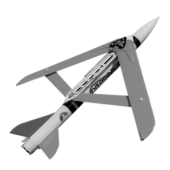
The Draco BG is a model boost glider (BG) based on the
real-life Boeing GBU-39 SDB (Small Diameter Bomb) which
originally was an air-drop ordinance and was later modified
for launching from ground vehicles. This modified version is
known as the GLSDB (Ground-Launched Small Diameter
Bomb) and is a precision weapon system that allows delivering
a payload of 93kg (205 lbs) to a location within a range of 150
km (93 mi) from the mobile launch platform. Development of
the GLSDB was a joint project of Boeing and the Saab Group.
The Draco BG copies the overall configuration of the GLSDB
and the unique folding wing arrangement.
Despite the fancy wing mechanism, flights of the Draco
BG model are simple. It launches upward on 24mm diam-
eter rocket motors. The simple interstage/wing-lock system
ensures reliable transition of the upper stage to glide configu-
ration while the booster recovers under a parachute. While a
challenging build, the Draco BG is a fantastic rocket for those
interested in mechanical design, gliders, and military history.
Needed Tools and Materials
… Hobby Knife with Sharp Blades
… Scissors
… Razor Saw
… Wood Glue
… Thin CyA Adhesive
… Medium CyA Adhesive
… Masking Tape
… Medium and Fine Sandpaper (180, 320 grit)
… Aluminum Angle
… 4-40 Tap
Kit #05065
Skill Level 5
Draco BG Parts List
Item # Item Name
10091 AT-24/3.75" (Motor Tube)
10151 AT-41.6/9" (Booster Tube)
10154 AT-41.6/18" LC (Fuselage Tube)
12976 #4 Flat Washer
12977 #4 3/16"x1/4" Unthreaded Off-White Nylon
Standoff
12978 #4 3/16"x5/32" Unthreaded Off-White Nylon
Standoff
12979 4-40 x 1/2 Black Nylon Panhead Screw
13031 CR-18/24
13035 CR-24/29
13123 AC-41.6/1.5" LC
13051 1/8" Launch Lug 1" Long
13056 1/4" Launch Lug 3" Long
14263 1/8" x 2.5" Wood Dowel
15015 CR-24/41.6 Cardstock (Rectangle)
15487 Draco BG Jig Sheet Cardstock
15488 Draco BG Parts Sheet A 1/8"x4" Balsa
15489 Draco BG Parts Sheet B 1/8" Ply
15490 Draco BG Parts Sheet C 1/16" Ply
15731 Draco BG Wing Sheet 1/8"x4" Balsa
15732 Draco BG Fin Sheet 1/8"x4" Balsa
15733 Draco BG Stabilizer Sheet 3/32"x4" Balsa
19469 PNC-41mm (BT-60)
24003 #117B Rubber Band
24044 Crimped "E-size" Engine Hook
29090 12" Printed Nylon Parachute
29518 100# Kevlar x 5 feet
29600 Clay Nose Wt 5g
31271 Instructions Sheet A
31272 Instructions Sheet B
31273 Instructions Sheet C
31274 Instructions Sheet D
31275 Instructions Sheet E
31276 Instructions Sheet F
39059 Face Card
41116 Decal Sheet
Optional Tools / Finishing Supplies
… Fin Alignment Guide (P/N 35546)
… Flat Needle File
… Wood Filler
… Sanding Sealer
… Extra Fine Sandpaper (600 grit)
… Spray Paint
… Wood Dowel
… Ruler or Calipers
Manufactured in the USA by:
Apogee Components Inc.
Colorado Springs, Colorado, USA
www.ApogeeRockets.com
Assembled In USA
Qty
1
1
1
4
5
2
7
1
1
1
2
2
2
1
1
1
1
1
2
1
1
1
1
1
1
1
1
1
1
1
1
1
1
1
1
Page 1
Advertisement

Related Manuals for Apogee DRACO BG


Summary of Contents for Apogee DRACO BG
- Page 1 15488 Draco BG Parts Sheet A 1/8”x4” Balsa Extremely Challenging 15489 Draco BG Parts Sheet B 1/8” Ply The Draco BG is a model boost glider (BG) based on the 15490 Draco BG Parts Sheet C 1/16” Ply real-life Boeing GBU-39 SDB (Small Diameter Bomb) which 15731 Draco BG Wing Sheet 1/8”x4”...
-
Page 2: Horizontal Stabilizer
Horizontal Stabilizer Launch Lug Horizontal Booster Fin This image outlines the basic nomenclature used in this instruction booklet for major parts of the Draco BG. Additional exploded views of the more complicated assemblies are included later. Assembly Booster Steps 1/4” (6mm) Step 1 1. - Page 3 2. Using a sharp hobby knife, remove the two CR-24/41.6 Step 2 centering rings from the small cardstock sheet (P/N 15015). 3. Install the motor hook by sliding it into the cut slot in the Step 3 tube with the hook end hanging over the aft end of the tube.
- Page 4 7. Put a ring of wood glue inside the front lip of the motor Step 7 tube. Seat the smaller green centering ring (CR-18/24) in the front of the motor mount tube with wood glue. Install the ring so that it sits against the engine hook so that it acts as an engine block.
- Page 5 12. Before removing the booster fins from the 1/8” balsa sheet Step 12 (P/N 15732), sand the surface smooth on both sides using a fine grit sandpaper (320 grit). 13. Remove the booster fins from the sheet using a hobby Step 13 knife and sand the edges of the parts to remove any rem- nants of tabs.
- Page 6 17. Remove the wing lock support frame (T) from the 1/16” Step 17 Wing lock support frame plywood sheet (P/N 15490). Using a small drop of wood glue at the front of each balsa support, slide the two wing lock assemblies as far as they will go into part T. Then glue the whole wing lock assembly onto the booster tube with the support frame 3/4”...
- Page 7 22. Apply a bead of wood glue to the inside of the short red Step 22 coupler tube at roughly the middle and slide the piston frame and ring assembly into the tube. To correctly align the frame and ring in the tube, place the tube and the flat end of the frame against the table so that they are flush.
- Page 8 27. The physical build of the booster is now complete and the Step 27 parachute and piston can be installed in the end of the tube to await finishing. Label Part 3x J Upper Wing Frame Main Wing Frame Forward Wing Frame Spacer Aft Wing Frame Spacer Forward Wing Frame Alignment Guide Aft Wing Frame Alignment Guide...
- Page 9 29. Apply a small amount of medium CyA adhesive to the slot Step 29 in the forward spacer C and install the tabs of the align- ment guide E (opposite the curved side) such that the tabs poke through the frame C and the curved portion is flush Flush with the surface of the balsa in the center.
- Page 10 34. Apply medium CyA adhesive to the slot and one surface of Step 34 the aft spacer (D) then slide it over the alignment tab (F). Step 35 35. Using a sharp hobby knife remove three of the bolt hex inserts (J) from the 1/8”...
- Page 11 Label Part Main Wing H1/H2 Root Pivot H1/H2 Hex Insert Stay Tip Pivot Stay Wing Stay Tip Spacer Stay Wing Stiffner/Pivot Main Wing Stiffner Wings: Step 39 39. Remove the root pivots (H1 & H2) from the 1/8” plywood sheet (P/N 15489) and the main wings (G) from the two 1/8”...
- Page 12 41. Remove the two stay tip pivots (K) from the 1/8” plywood Step 41 sheet (P/N 15489) and press them into place on both main wings. Secure them in place by wicking thin CyA adhesive around the edges of K. 42.
- Page 13 46. Apply a thin layer of wood glue to the tip spacers (M) and Step 46 attach to the outer tips of each stay wing flush with the outer radius. For maximum strength, rotate the spacers so that the grain in the spacers is at a 90 degree angle to the grain in the stay wings.
- Page 14 51. Remove the tape from the main wings, then shape each Step 51 wing into a flat bottom airfoil where the wing stiffeners are facing up. Use medium sandpaper (180 grit) to round the leading edge of the wing then taper the aft 2/3rds of the wing down to a thickness of at most 1/32”...
- Page 15 56. Remove the four pieces of the stabilizer alignment jig from Step 56 the cardstock sheet (P/N 15487) and assemble the jig. Press the tabs in the standoffs through the slots in each alignment plate then secure the jig by wicking a small amount of thin CyA adhesive in each joint.
- Page 16 61. Using a razor saw, remove the entire smaller shoulder of Step 61 the transition by cutting along the small depression right at the joint between the shoulder and the transition surface. If necessary, sand the cut end and inner edge of the transi- tion with fine sandpaper (320 grit) to smooth any inconsis- tencies in the cut.
- Page 17 Run a bead of wood glue along the joint then shape the fillet with the tip of a finger. Painting: 67. Painting of the Draco BG is easier before the wing frame Step 67 Mask gluing areas is glued into place.
- Page 18 71. Prior to spraying the Draco, the interior of the tube can be Step 71 protected by stuffing a couple of folded paper towels into the slot on the back. Apply primer first, and then paint to the wings, fuselage, wing tie, and booster, sanding be- tween coats to achieve a smooth coat on all surfaces while using only the minimal paint possible.
- Page 19 75. Remove the paint mask from the fuselage and wood glue Step 75 the wing frame onto the fuselage, aligning it using the alignment tabs and ensuring that it sits at a right angle to the vertical stabilizer. Allow the frame to dry completely before continuing.
- Page 20 80. Check that the wings retract uniformly, sitting flush with the Step 80 vertical stabilizer. There should be no gap on either side. If the wings are uneven because the teeth are misaligned, remove one wing and adjust its position slightly. Once the Even spacing wings retract correctly, tighten all three screws in the wing tie and do a final check that the wings move smoothly with...
- Page 21 Step 87 87. At this point, once the booster is added, the Draco BG is physically complete, but the glider must be trimmed for correct flight before it can be launched under power.
- Page 22 Type Altitude Altitude the descent rate is correct using the procedure in step 90 (ft.) and adjust as needed. Estes C11-3 Estes D12-3 Aerotech D15T-4 Reloadable Quest D22W-4 The Draco BG is now ready for flight! Estes E12-4 Page 22...
- Page 23 Launch Supplies Needed Step A To launch your rocket you will need: • A launch pad with a 1/4” (3 mm) launch rod and a launch controller that can handle the selected igniters • Recovery Wadding • Engines such as those recommended in the motor chart. Additional motors can be viewed at: https://www.apo- geerockets.com/Model-Rocket-Kits/Skill-Level-5-Mod-...
- Page 24 Countdown and Launch Procedure The Draco BG is a fairly low flying rocket that is highly affected by wind so it should be flown in low wind or on still days whenever possible. Even then, it is preferable to fly on a large field as a glider can easily travel a long way if not trimmed for a spiraling glide.
Need help?
Do you have a question about the DRACO BG and is the answer not in the manual?
Questions and answers