Table of Contents
Advertisement
Quick Links
Skill Level 2
Easy to Construct and Fly
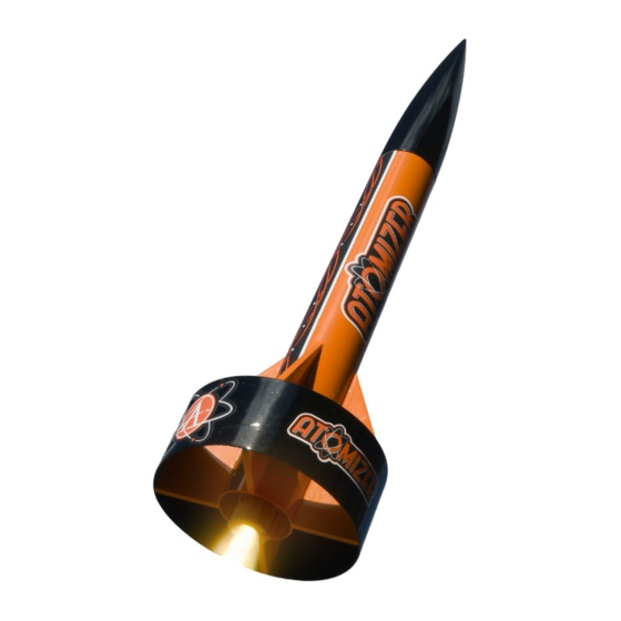
The first thing you'll notice on the Atomizer is the ring-tail
at the base. This large annular wing provides extra stability
because it increases the amount of fin area. The other thing it
does is to protect the fins from a hard landing and makes them
much stronger than traditional rockets. What's not to love about
a stronger rocket that flies straighter?
The Atomizer is easy to build, although it is recommended to
those modelers that have previous rocketry experience in the
past. The additional ring on the rear of the rocket may require
sanding down the tips of the fins just slightly in order to achieve
a perfect fit. The rocket has a very simple but attractive color
scheme that will remind you of a hot rod for outer space. You'll
love the simple vinyl decals that give the rocket lots of appeal
with minimum effort. Your friends are going to love this model
too!
Sheet A - P/N 31072
Kit #05054
Skill Level 2
Atomizer Parts List
Item # Item Name
10068 AT-18/2.75"
10120 AT-33/9 etched tube
13029 CR-13/18 Blue Ring
13031 CR-18/24 Green Ring
13051 1/8" Launch Lug 1" Long
13304 CR-18/33 Cardstock Sheet
15553 Atomizer Fin Sheet ⅛" x 3" x 9"
19468 PNC-33mm
24043 Regular Crimped Engine Hook
29124 12" Parachute Pack
29518 100# Kevlar Shock Cord x 5ft
31072 Atomizer Instruction Sheet A
31073 Atomizer Instruction Sheet B
31152
AT-3.71"/1.5"
35592 Display Stand Sheet
39044 Atomizer Facecard
41098 Atomizer Decal
Needed Tools and Materials
… Pencil
… Ruler with a straight edge
… Scissors
… Hobby Knife with Sharp Blades
… Wood Glue
… Super Glue (CyA adhesive – medium viscosity)
… Aluminum "Angle" to draw lines on the tube
Optional Tools / Finishing Supplies
… Masking Tape
… Paper Towels
… Bowl of water with a little dishwashing soap
… Paint Supplies: Spray Paint, Brushes, etc
… Sandpaper 220 grit and 400 grit and Sanding Block
Manufactured in the USA by:
Apogee Components Inc.
Colorado Springs, Colorado, USA
Visit us online at:
www.ApogeeRockets.com
Made In USA
Qty
1
1
1
1
2
1
1
1
1
1
1
1
1
1
1
1
1
Page 1
Advertisement
Table of Contents

Related Manuals for Apogee Atomizer 05054


Summary of Contents for Apogee Atomizer 05054
- Page 1 Your friends are going to love this model Manufactured in the USA by: too! Apogee Components Inc. Colorado Springs, Colorado, USA Visit us online at: Page 1 www.ApogeeRockets.com...
- Page 2 Assembly Steps … 1. Fine sand the balsa fin sheet with 400 grit sandpa- per using a sanding block or Apogee’s Sanding Tee. Carefully remove all the fins from the fin sheet by free- ing the edges with a sharp hobby knife. Also remove the cardstock centering rings from the sheet.
- Page 3 … 6. Take the blue ring and glue it inside the front end of the tube using wood glue. You can use a rocket engine to push it in until it butts against the metal en- gine hook tang on the inside of the tube. Remove the rocket engine casing immediately, and wipe away the excess glue on both sides of the engine block.
- Page 4 … 11. Using wood glue, attach the fins to the rocket along the lines drawn previously. The aft edges of the fins should be even with the aft edge of the body tube. For straighter flights, check to make sure the fins are perpendicular to the tube.
- Page 5 … 17. Find the white cotton shroud line and cut the string into three equal lengths as shown. Tie the shroud lines through the ring holes as shown. Put a little bit of glue on the knots to secure them in place. Allow the glue to dry.
- Page 6 Display Stand Assembly Display Stand Assembly … Remove the display stand pieces from the laser-cut sheet. Assemble the leg pieces together. Run a thin bead of wood glue along all the joints between the pieces. When the glue is dry, the stand can be painted and a rocket can be placed on it.
- Page 7 … C. When you are ready to launch your rocket, slide the rocket motor into the engine mount tube until the engine hook clicks into place as seen below. Step C … D. Insert and secure the engine igniter as directed on the package the engines came with.
- Page 8 Misfire Procedure Misfire Procedure Occasionally the igniter will burn, but the motor will fail to ignite. If this happens, the cause is that the pyrogen on the igniter was not in contact with the engine's propellant. When an ignition failure occurs, remove the safety key from the launch controller and wait 60 seconds before approaching the rocket.
Need help?
Do you have a question about the Atomizer 05054 and is the answer not in the manual?
Questions and answers