
Related Manuals for Vents TwinFresh Atmo Wi-Fi


Summary of Contents for Vents TwinFresh Atmo Wi-Fi
- Page 1 USER’S MANUAL TwinFresh Atmo Wi-Fi TwinFresh Atmo Wi-Fi mini TwinFresh Atmo Wi-Fi M TwinFresh Atmo Wi-Fi mini M Single-room reversible energy recovery ventilator...
-
Page 2: Table Of Contents
Atmo Wi-Fi (mini) (M) CONTENTS Safety requirements ..................................2 Purpose ........................................ 4 Delivery set ......................................4 Designation key ....................................4 Technical data ....................................5 Unit design and operating principle ..........................6 Installation and set-up................................9 Connection to power mains ..............................14 Technical maintenance ................................ - Page 3 Do not use the unit in a hazardous or explosive environment containing spirits, gasoline, insecticides, etc. Do not close or block the intake or extract vents in order to ensure the efficient air flow. Do not sit on the unit and do not put objects on it.
-
Page 4: Purpose
M – no shutters, the airflow can only be blocked manually using the front panel Ventilator series TwinFresh Atmo Wi-Fi – a series of reversible ventilators controlled via Wi-Fi with a duct diameter of 160 mm and a nominal capacity of 50 m TwinFresh Atmo Wi-Fi mini –... -
Page 5: Technical Data
TECHNICAL DATA The temperature in the room where the indoor unit of the ventilator is installed must be in the range from +1 ˚C to +40 ˚C with relative humidity up to 65 % (no condensation build-up). The temperature of the transported air should be in the range from -15 ˚С to +40 ˚C. If the conditions of use of the ventilator are outside the specified limits, turn off the ventilator. -
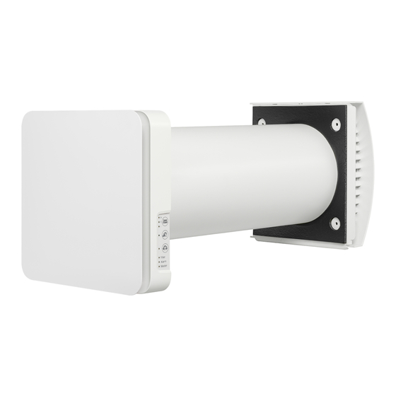
Page 6: Unit Design And Operating Principle
The ventilator consists of an indoor unit with a decorative front panel, a fan unit, a heat exchanger unit, located inside the air duct and the outer ventilation hood. TwinFresh Atmo Wi-Fi mini TwinFresh Atmo Wi-Fi mini M In the models, the fan and heat exchanger units are combined in a single cartridge. - Page 7 Operating principle of TwinFresh Atmo Wi-Fi and TwinFresh Atmo Wi-Fi mini ventilator shutters The indoor unit of these models is equipped with automatic shutters. During the ventilator operation the automatic shutters are opened and let the air flow freely through the ventilator. The automatic shutters are closed for 2 minutes at the ventilator shut down.
- Page 8 If necessary, you can set different ventilator speeds for different time intervals by day of the week in the «Weekly Schedule» section of the Vents Home mobile app. For the week schedule to work correctly, you need to set the current date and time correctly in the «Date and Time»...
-
Page 9: Installation And Set-Up
Indoor unit Indoor unit Ventilator model or installation variant Reference dimensions for installation of ventilators TwinFresh Atmo Wi-Fi mini TwinFresh Atmo Wi-Fi Length of cartridge or fan and regenerator units [mm] Hole diameter D [mm] Minimum possible wall thickness when using AH,... - Page 10 Atmo Wi-Fi (mini) (M) 1. Prepare a round core hole in the outer wall. The figure below shows the minimum distance from the hole to the surrounding objects. The hole diameter depends on the specific ventilator model. The corresponding values are given in the table. min 300 ø...
- Page 11 5. Separate the front panel of the indoor unit from its back part. To do this, press the round buttons on the top and bottom of the indoor unit simultaneously, as shown on the left in the figure below. 6. Remove the three retaining screws from the controller cover to enable access to the terminals. Route the power wires through the appropriate cable glands.
- Page 12 Atmo Wi-Fi (mini) (M) 8. Route the power cable as figured below and connect the ventilator to power mains in compliance with the external wiring diagram, see section Connection to power mains. Secure the power cable with the clamp. Controller board 9.
- Page 13 Insert the sound-absorbing layer in the air duct. Roll the layer of the sound absorbing material to match the air duct diameter. The protecting paper layer must be outside. Insert the sound absorbing roll into the cartridge against stop. Make a mark at the end of the air duct, remove the material and cut the roll as marked.
-
Page 14: Connection To Power Mains
Atmo Wi-Fi (mini) (M) CONNECTION TO POWER MAINS The ventilator is rated for connection to single-phase AC 100-240 V/50 (60) Hz power mains. For electric installations use insulated, flexible conductors (cables, wires) with the minimum cross section of 0.5 up to 0.75 mm power cables and 0.25 mm for sensor cables. - Page 15 PRE-SETTING OF THE VENTILATOR Prior to operating the ventilator set it up using the DIP switch. It is located on the controller circuit board. To access the DIP switch, take off the front panel of the indoor unit and uplift the rubber plug that covers the switch.
- Page 16 Atmo Wi-Fi (mini) (M) The figure below shows the control buttons on the indoor unit and the remote control with a brief description of their function. Turning the ventilator on/o Speed/Standby The speed selection sequence is as follows: I-II-III-Standby. Speed selection Regeneration mode In this mode the unit switches between the supply and the extraction modes...
- Page 17 VENTILATOR CONTROL WITH THE BUTTONS ON THE INDOOR UNIT The table below shows the buttons and indicators on the indoor ventilator unit with a detailed description of their purpose and functionality. The speed selection sequence is follows: I-II-III-Standby. All ventilators combined into one network run at the speed set by the master ventilator.
- Page 18 Press any speed setting key to deactivate the timer or press the timer control button once again. VENTILATION UNIT OPERATION WITH THE MOBILE APPLICATION VENTS HOME Download the Vents Home application and install it on the mobile device. Vents Home – App Store Vents Home –...
- Page 19 WIRELESS CONNECTION OF SEVERAL VENTILATORS Ventilators can be combined into a group in which one ventilator shall act as the master and the others shall be connected to it as slaves. master If the ventilator is a ventilator, the slave ventilators and mobile devices connect to it via Wi-Fi. The master ventilator is controlled using a mobile device, remote control or touch buttons on the ventilator casing.
- Page 20 Atmo Wi-Fi (mini) (M) VENTILATOR WIRELESS CONNECTION DIAGRAMS Wiring diagram 1 Connection of up to 8 Slave units or mobile devices to the Master unit with its own wireless Master with a Wi-Fi access point access point. In case of connection of 8 Slave units to the Master unit with its own wireless access point a mobile device may not be connected.
- Page 21 Set the DIP switches on each ventilator to the position that corresponds to its role in the group (see «Position of the DIP switch»). • Next, configure the Wi-Fi settings of the master ventilator by following the instructions in the Vents Home mobile app. •...
-
Page 22: Technical Maintenance
Atmo Wi-Fi (mini) (M) TECHNICAL MAINTENANCE DISCONNECT THE UNIT FROM POWER SUPPLY BEFORE ANY MAINTENANCE OPERATIONS! MAKE SURE THE UNIT IS DISCONNECTED FROM POWER MAINS BEFORE REMOVING THE PROTECTION Maintenance of the ventilator means regular cleaning of the ventilator surfaces of dust and cleaning and replacement of the filters. To enable access to the main units, follow the procedure described below. - Page 23 4. Clean filters once they become dirty. Upon elapse of the set number of days the filter replacement indicator (Filter) starts glowing. Depending on the dustiness of the air, the duration of the ventilator operation until the next filter cleaning may be different. The duration of the period when the filter replacement indicator is turned on can be set using the mobile application in the range from 70 to 365 days of continuous operation (by default, the Manufacturer’s recommended value is set to 90 days).
-
Page 24: Storage And Transportation Regulations
Atmo Wi-Fi (mini) (M) POSSIBLE FAULTS AND TROUBLESHOOTING Problem Possible reasons Troubleshooting Make sure the power supply line is connected No power supply. correctly, otherwise troubleshoot the connection When switching on the error. ventilator, the fan does not Turn the ventilator off. Troubleshoot the motor jam start. -
Page 25: Manufacturer's Warranty
MANUFACTURER’S WARRANTY The product is in compliance with EU norms and standards on low voltage guidelines and electromagnetic compatibility. We hereby declare that the product complies with the provisions of Electromagnetic Compatibility (EMC) Directive 2014/30/EU of the European Parliament and of the Council, Low Voltage Directive (LVD) 2014/35/EU of the European Parliament and of the Council and CE-marking Council Directive 93/68/EEC. - Page 26 Atmo Wi-Fi (mini) (M) www.ventilation-system.com...
-
Page 27: Certificate Of Acceptance
CERTIFICATE OF ACCEPTANCE Unit Type Single-room reversible energy recovery ventilator Model Serial Number Manufacture Date Quality Inspector’s Stamp SELLER INFORMATION Seller Address Phone Number E-mail Purchase Date This is to certify acceptance of the complete unit delivery with the user’s manual. The warranty terms are acknowledged and accepted. - Page 28 V268EN-01...
Need help?
Do you have a question about the TwinFresh Atmo Wi-Fi and is the answer not in the manual?
Questions and answers