Advertisement
Quick Links
Advertisement

Related Manuals for Vents TT PRO


Summary of Contents for Vents TT PRO
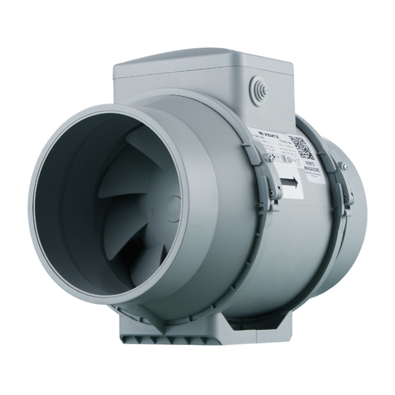
- Page 1 INLINE MIXED-FLOW FANS TT PRO User’s manual www.ventilation-system.com...
-
Page 2: Table Of Contents
This user’s manual is a main operating document intended for technical, maintenance, and operating staff. The manual contains information about purpose, technical details, operating principle, design, and installation of the TT PRO unit and all its modifications. Technical and maintenance staff must have theoretical and practical training in the field of ventilation systems and should be able to work in accordance with workplace safety rules as well as construction norms and standards applicable in the territory of the country. - Page 3 TO AVOID A RANDOM RESTART OF THE THERMAL SWITCH, THE UNIT MUST NOT BE POWERED THROUGH AN EXTERNAL SWITCHING DEVICE, SUCH AS A TIMER, OR CONNECTED TO POWER MAINS USUALLY TURNED ON/OFF BY PUBLIC SERVICES. READ THE USER’S MANUAL CAREFULLY BEFORE PROCEEDING WITH INSTALLATION WORKS. COMPLIANCE WITH THE MANUAL REQUIREMENTS ENSURES RELIABLE OPERATION AND LONG SERVICE LIFE OF THE UNIT.
- Page 4 • Fixed electrical wiring must be equipped with an automatic circuit breaker. • The unit must be connected to power mains through a double pole circuit breaker integrated into the fixed wiring system with opening of contacts at all poles. The gap between the circuit breaker contacts at all poles must be not less than 3 mm.
- Page 5 • For effective functioning of the unit, it is necessary to ensure an appropriate fresh air supply into the room. Do not close or block the intake or extract vents in order to ensure the efficient air flow. • Do not sit on the unit and do not put objects on it.
- Page 6 document’s preparation. • The Company reserves the right to modify the technical characteristics, design, or configuration of its products at any time in order to incorporate the latest technological developments. • No part of this publication may be reproduced, stored in a retrieval system, or transmitted, in any form or by any means in any information search system or translated into any language in any form without the prior written permission of the Company.
-
Page 7: Delivery Set
The fan is designed for connection to ø 100, 125, 150, 160, 200, 250 and 315 mm air ducts. The unit is equipped with a two speed motor. Ø D 195,8 226/255* 302,5 TT PRO 100 195,6 226/255* 258,5 TT PRO 125 220,1... -
Page 8: Operation Guidelines
OPERATION GUIDELINES The fan is rated for connection to single-phase AC 220-240 V/50 Hz or 220 V/60 Hz power mains. The unit is rated for continuous operation. The arrow on the fan casing must match the air direction in the system. Ingress protection rating against access to hazardous parts and water ingress is IPX4. -
Page 9: Designation Key
DESIGNATION KEY TT PRO Modifications: timer speed switch speed controller with an electronic thermostat and a temperature sensor integrated inside an air duct. Temperature-based operation logic speed controller with an electronic thermostat and an outdoor temperature sensor fixed on a 4 m cable. Temperature-based operation logic speed controller with an electronic thermostat and an integrated temperature sensor. - Page 10 MOUNTING The fan is suitable both for horizontal or vertical mounting on the floor, on the wall or on the ceiling (Fig. 1). The fan can be installed independently or as part of a set with parallel or in-series connection (Fig. 2). Install minimum 1 m long air duct on the intake spigot side in case of horizontal fan mounting or a hood in case of vertical fan mounting.
- Page 11 CONTROL LOGIC TT PRO XXX T fan starts running after the external switch supplies control signal to the LT input terminal (for example, during turning the light on). After removal of the control signal the fan continues to run within the set time (adjustable with the turn-off delay timer from 2 to 30 minutes).
- Page 12 The fan functioning logic may be based on temperature or timer controls: TT PRO XXX U(n): the fan switches to the maximum speed as the room air temperature exceeds the set point. As the air temperature drops down 2 °C below the temperature set point or if the initial temperature is below the set point, the fan operates with the set speed.
-
Page 13: Technical Maintenance
TECHNICAL MAINTENANCE The fan surfaces must be regularly cleaned (once in 6 months) from dirt and dust (Fig. 24-30). Disconnect the fan from power mains prior to any maintenance operations. To clean the fan, use a soft cloth or a brush wetted in a mild detergent solution. -
Page 14: Storage And Transportation Regulations
STORAGE AND TRANSPORTATION REGULATIONS • Store the unit in the manufacturer’s original packaging box in a dry closed ventilated premise with temperature range +5...+40 ˚С and relative humidity up to 70 %. • Storage environment must not contain aggressive vapors and chemical mixtures provoking corrosion, insulation, and sealing deformation. -
Page 15: Manufacturer's Warranty
MANUFACTURER’S WARRANTY The product is in compliance with EU norms and standards on low voltage guidelines and electromagnetic compatibility. We hereby declare that the product complies with the provisions of Electromagnetic Compatibility (EMC) Directive 2014/30/ EU of the European Parliament and of the Council, Low Voltage Directive (LVD) 2014/35/EU of the European Parliament and of the Council and CE-marking Council Directive 93/68/EEC. - Page 16 • Redesign or engineering changes to the unit. • Replacement and use of any assemblies, parts and components not approved by the manufacturer. • Unit misuse. • Violation of the unit installation regulations by the user. • Violation of the unit control regulations by the user. •...
- Page 17 min 1 m...
- Page 20 TT PRO XXX MAX / MIN...
- Page 21 TT PRO XXX T MAX / MIN MAX / MIN TERMINAL BLOCK FOR 4 CONTACTS TERMINAL BLOCK FOR 5 CONTACTS...
- Page 23 STOP...
- Page 24 Speed control knob TT PRO U (U1) TT PRO UN (U1N) Thermostat control knob TT PRO P Speed control knob...
- Page 27 Quality Inspector’s Stamp Sold by (name and stamp of the seller) Manufacture Date Purchase Date...
- Page 28 Certificate of acceptance TT PRO The fan is recognized as serviceable V77EN-04...
Need help?
Do you have a question about the TT PRO and is the answer not in the manual?
Questions and answers