
Subscribe to Our Youtube Channel
Related Manuals for Vents TwinFresh Expert


Summary of Contents for Vents TwinFresh Expert
- Page 1 USER’S MANUAL TwinFresh Expert Single-room reversible energy regeneration ventilator F112EN-02.indd 1 05.10.2015 16:09:51...
-
Page 2: Table Of Contents
TwinFresh Expert, (hereinafter « the unit» as mentioned SAFETY REQUIREMENTS Read the user’s manual carefully prior to installing and operating the unit. - Page 3 • Do not operate the unit outside the temperature range stated in the user’s • Do not use damaged equipment or cables manual. when connecting the unit to power mains. • Do not operate the unit in aggressive or explosive environments. •...
-
Page 4: Purpose
Installation instruction for the ventilation hood 1 item Packing box 1 item DESIGNATION KEY TwinFresh Expert R A 1 - 50 L - 2 Ventilation hood model _ — EH white 160— 2 — EH-2 white 160 Air duct length _ —... -
Page 5: Main Technical Parameters
TECHNICAL DATA The ventilator is rated for indoor application with the ambient temperature ranging from -30 C (-22 F) up to +50 C (+122 F) and relative humidity up to 97%. The ventilator is rated as a class II electric appliance. Ingress Protection (IP) rating from solid objects and liquids IP 24. -
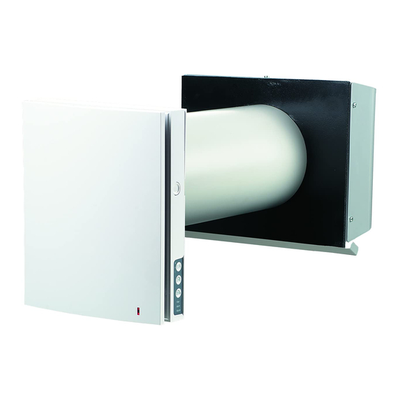
Page 6: Design And Operating Logic
DESIGN AND OPERATING LOGIC The ventilator consists of an indoor assembly unit with a decorative front panel, a cartridge, an air duct, a sound absorbing material and an outer ventilation hood. Cartridge is the basic functioning part of the ventilator. The cartridge consists of the fan, the regenerator and two filters that ensure rough air filtration and prevent ingress of dust and foreign objects into the regenerator and the fan. - Page 7 OPERATING LOGIC OF THE AUTOMATIC SHUTTERS The indoor assembly unit is equipped with automatic shutters. During the ventilator standby the automatic shutters open and let free air flow through the ventilator. The automatic shutters close 2 minutes after shutdown of the ventilator. Shutters closed Shutters opened VENTILATOR OPERATION MODES...
-
Page 8: Mounting And Set-Up
MOUNTING AND SET-UP READ THE USER’S MANUAL PRIOR TO MOUNTING THE VENTILATOR. ATTENTION! DO NOT BLOCK THE AIR DUCT OF THE INSTALLED VENTILATOR WITH DUST ACCUMULATING MATERIALS, SUCH AS CURTAINS, CLOTH SHUTTERS, ETC. AS IT PREVENTS AIR CIRCULATION IN THE ROOM. 1. - Page 9 3. Stick the delivered cardboard master plate on the indoor wall using a mounting tape. The large opening in the master plate must be axially aligned with the air duct. For aligning of the mater plate with respect to the horizon line it is recommended to use a builder’s level.
- Page 10 7. Insert the cartridge into the air duct as figured below. The pointer must be directed upwards. Then fix the wire with the protruding clamp and connect the socket connector to the circuit board. The pointer must be directed upwards. Insert the wires under the cable clamp and connect the socket connector to the...
-
Page 11: Unit Connection And Control
CONNECTION TO POWER MAINS AND CONTROL DISCONNECT THE UNIT FROM POWER SUPPLY PRIOR TO ANY ELECTRIC INSTALLATION OPERATIONS. INSTALLATION SHALL ONLY BE PERFORMED BY A PROFESSIONAL ELECTRICIAN QUALIFIED FOR UNASSISTED OPERATIONS WITH ELECTRICAL INSTALLATIONS UP TO 1000 V AFTER CAREFUL STUDY OF THE PRESENT USER’S MANUAL. THE RATED ELECTRICAL PARAMETERS ARE STATED ON THE RATING PLATE. - Page 12 WIRING DIAGRAM FOR IN-SERIES CONNECTION Master Slave 1 Slave N Power input +12V +12V +12V 100-230 V / 50-60 Hz to the next ventilator WIRING DIAGRAM FOR PARALLEL CONNECTION Master Slave 1 Slave N Power input +12V +12V +12V 100-230 V / 50-60 Hz to the next ventilator VENTILATOR SET-UP Prior to operating the ventilator set up the ventilator...
- Page 13 Turning the ventilator off is not allowed. The switch position disables deactivation of the ventilator with the button on the side control panel. Fan rotation direction: For controlled ventilation it is recommended to install the ventilators pairwise and integrate them in a group using a signalling cable. Set one half of the connected ventilators into supply mode and the other half into extract mode.
- Page 14 VENTILATOR CONTROL WITH THE BUTTONS ON THE INDOOR ASSEMBLY UNIT The speed setting engages cyclically: I-II-III-Off. All the connected in series ventilators synchronise their speed with the first ventilator in the group. Regeneration mode The ventilator operates 70 seconds in supply mode and 70 seconds in extract mode. Heat regeneration is performed in this mode.
-
Page 15: Maintenance
MAINTENANCE DISCONNECT THE UNIT FROM POWER SUPPLY BEFORE ANY MAINTENANCE OPERATION WITH THE UNIT. Maintenance of the ventilator means regular cleaning of the ventilator surfaces of dust and cleaning or replacement of the filters. To access the basic assembly units follow the steps: 1. - Page 16 Clean the filters as often as those gets soiled, but at least 3-4 times a year. After the set filter replacement periodicity has expired the Filter indicator starts glowing. • • The filter timer is reset once the socket connector of the cartridge is disconnected from the circuit board. Wash the filters and let them get dry.
-
Page 17: Troubleshooting
TROUBLESHOOTING POSSIBLE FAULTS AND TROUBLESHOOTING Fault Possible reasons Remedy Make sure that the ventilator is properly No power supply. connected to power mains and make any corrections, if necessary. The fan does not start up during start-up of the Turn the ventilator off. ventilator. -
Page 18: Manufacturer's Warranty
MANUFACTURER’S WARRANTY The manufacturer hereby warrants normal operation of the unit for 24 months after the retail sale date provided the user’s observance of the transportation, storage, mounting and operation regulations. Should any malfunctions occur in the course of the unit operation through the Manufacturer’s fault during the guaranteed period of operation the user is entitled to elimination of faults by the manufacturer by means of warranty repair at the factory free of charge. -
Page 19: Acceptance Certificate
Customer's Signature Seller’s Stamp INSTALLATION CERTIFICATE The single-room reversible energy regeneration ventilator TwinFresh Expert _________has been connected to power mains pursuant to the requirements stated in the present user’s manual. Discretionary repair of the unit by the user. -
Page 20: Warranty Card
WARRANTY CARD Unit Type The single-room reversible energy regeneration ventilator Model TwinFresh Expert ______________ Serial Number Manufacture Date Purchase Date Warranty Period Seller Seller’s Stamp F112EN-02 F112EN-02.indd 20 05.10.2015 16:10:24...
Need help?
Do you have a question about the TwinFresh Expert and is the answer not in the manual?
Questions and answers