
Related Manuals for Vents TwinFresh Atmo


Summary of Contents for Vents TwinFresh Atmo
- Page 1 USER’S MANUAL TwinFresh Atmo TwinFresh Atmo mini TwinFresh Atmo M TwinFresh Atmo mini M Single-room reversible energy recovery ventilator...
-
Page 2: Table Of Contents
Atmo (mini) (M) CONTENTS Safety requirements ..................................2 Purpose ........................................ 4 Delivery set ......................................4 Designation key ....................................4 Technical data ....................................5 Design and operating principle ............................6 Mounting and set-up .................................. 9 Connection to power mains ..............................14 Technical maintenance ................................ - Page 3 Do not use the unit in a hazardous or explosive environment containing spirits, gasoline, insecticides, etc. Do not close or block the intake or extract vents in order to ensure the efficient air flow. Do not sit on the unit and do not put objects on it.
-
Page 4: Purpose
М – shutters not included, air flow is only blocked manually via the front panel Ventilator series TwinFresh Atmo is a series of reversible ventilators with duct diameters of 160 mm and rated air flow of 50 m TwinFresh Atmo mini is a series of reversible ventilators with duct diameters of 100 mm and rated air flow of 25 m www.ventilation-system.com... -
Page 5: Technical Data
The unit design is constantly being improved, thus some models may be slightly different from those described in this manual. OVERALL DIMENSIONS OF THE INDOOR UNIT [MM] ø 160 (TwinFresh Atmo models) ø 103 (TwinFresh Atmo mini models) www.ventilation-system.com... -
Page 6: Design And Operating Principle
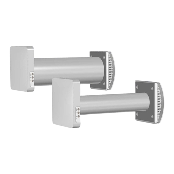
The ventilator consists of an indoor unit with a decorative front panel, a fan unit, a regenerator unit, which are installed inside the air duct, and an outer ventilation hood. TwinFresh Atmo mini TwinFresh Atmo mini M models, the fan unit and the regenerator unit are combined to form a non- separable cartridge. - Page 7 Operating logic of the automatic shutters in the TwinFresh Atmo and TwinFresh Atmo mini ventilators The indoor unit is equipped with automatic shutters. During the ventilator operation the automatic shutters are opened and let the air flow freely through the ventilator. It takes 2 minutes for the shutters to close upon ventilator shutdown.
- Page 8 Atmo (mini) (M) VENTILATOR OPERATION MODES Ventilation: the ventilator runs either in air extraction or air supply mode at a set speed. In this mode some of the ventilators in the network run in air supply mode and the other ones in air extraction mode, depending «Setting ventilator operation modes using DIP switches»).
-
Page 9: Mounting And Set-Up
The length of the internal elements, the diameter of the required opening and the minimum wall thickness in which the ventilator can be installed when using different external ventilation hoods are shown in the table below. Layout of the ventilator units inside the wall TwinFresh Atmo mini TwinFresh Atmo Air duct length... - Page 10 Atmo (mini) (M) 1. Prepare a round core hole in the outer wall. The figure below shows the minimum distance from the hole to the surrounding objects. The hole diameter depends on the specific ventilator model. The corresponding values are given in the table. min 300 ø...
- Page 11 Hole marking for unit fastening 50.5 Entrance for wiring 86.5 95.5 5. Separate the front panel of the indoor unit from its back part. To do it, simultaneously press the round keys in the top and bottom parts of the indoor unit, as illustrated on the left-hand side of the picture below. 6.
- Page 12 Atmo (mini) (M) 7. Fix the back part of the indoor unit on the wall with the screws supplied with the mounting kit of the ventilator. 8. Route the power cable as figured below and connect the ventilator to power mains in compliance with the external wiring diagram, refer to the Connection to power mains section.
- Page 13 10. Install the cartridge or the regenerator unit and the fan unit into the air duct as figured below and connect the connector to the board as shown by the arrow. Insert the sound-absorbing layer into the air duct. Roll the layer of the sound-absorbing material to match the air duct diameter. The protecting paper layer must be outside.
-
Page 14: Connection To Power Mains
Atmo (mini) (M) CONNECTION TO POWER MAINS The ventilator is rated for connection to AC 100-240 V/50 (60) Hz power mains. For electric installations use insulated, flexible conductors (cables, wires) with the minimum cross section of 0.5 up to 0.75 mm power cables and 0.25 mm for sensor cables. - Page 15 Grouping the ventilators in a network For group control over multiple ventilators, they need to be grouped in a network. A possible network grouping example is illustrated in the figure below. The ventilators can be connected in series and branching chains (ventilators No. 2 and No. 3 in the figure). Warning! Do not connect more than two input cables to a single output when branching! IN-terminal The network can only have one Master ventilator (it is determined as the one, whose...
- Page 16 Atmo (mini) (M) VENTILATOR SETUP Prior to operating the ventilator set up the ventilator using the DIP switch. It is located on the controller circuit board. To access the DIP switch, take off the front panel of the indoor unit and uplift the rubber plug that covers the switch.
- Page 17 VENTILATOR CONTROL The ventilator is controlled with the remote control or keys on the side surface of the indoor unit (see the figure below). When ventilators are connected in a single network, the controls only impact the first (Master) ventilator. Turning the ventilator on/o Speed/Standby The speed selection sequence...
- Page 18 Atmo (mini) (M) VENTILATOR CONTROL WITH THE BUTTONS ON THE INDOOR UNIT The table below shows the buttons and indicators on the indoor ventilator unit with a detailed description of their purpose and functionality. The ventilator speed selection sequence is as follows: I-II-III-Standby. All the units integrated in a single network operate according to the speed settings of the Master unit.
-
Page 19: Technical Maintenance
TECHNICAL MAINTENANCE DISCONNECT THE UNIT FROM POWER SUPPLY BEFORE ANY MAINTENANCE OPERATIONS! MAKE SURE THE UNIT IS DISCONNECTED FROM POWER MAINS BEFORE REMOVING THE PROTECTION. Maintenance of the ventilator means regular cleaning of the ventilator surfaces of dust and cleaning and replacement of the filters. Upon elapse of the set filter service life (90 days) the Filter indicator starts shining. - Page 20 Atmo (mini) (M) 4. Clean the filters as they get clogged. Depending on the dustiness of the air, the duration of the ventilator operation until the next filter cleaning may be different. • Wash the filters and let those dry out completely. •...
-
Page 21: Storage And Transportation Regulations
POSSIBLE REASONS AND TROUBLESHOOTING Problem Possible reasons Troubleshooting Make sure the power supply line is connected No power supply. correctly, otherwise troubleshoot the connection When switching on the error. ventilator, the fan does not Turn the ventilator off. Troubleshoot the motor jam start. -
Page 22: Manufacturer's Warranty
Atmo (mini) (M) MANUFACTURER’S WARRANTY The product is in compliance with EU norms and standards on low voltage guidelines and electromagnetic compatibility. We hereby declare that the product complies with the provisions of Electromagnetic Compatibility (EMC) Directive 2014/30/EU of the European Parliament and of the Council, Low Voltage Directive (LVD) 2014/35/EU of the European Parliament and of the Council and CE-marking Council Directive 93/68/EEC. -
Page 23: Certificate Of Acceptance
CERTIFICATE OF ACCEPTANCE Unit Type Single-room reversible energy recovery ventilator Model Serial Number Manufacture Date Quality Inspector’s Stamp SELLER INFORMATION Seller Address Phone Number E-mail Purchase Date This is to certify acceptance of the complete unit delivery with the user’s manual. The warranty terms are acknowledged and accepted. - Page 24 V268-1EN-01...
Need help?
Do you have a question about the TwinFresh Atmo and is the answer not in the manual?
Questions and answers