
Related Manuals for Electrolux Professional TD6-6LAB


Summary of Contents for Electrolux Professional TD6-6LAB
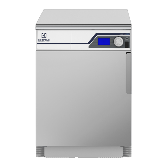
- Page 1 Installation manual Tumble dryer TD6–6 LAB Type N1130.. 438917600/GB, IE Original instructions 2023.12.22...
-
Page 3: Table Of Contents
Contents Contents 1 Safety Precautions ..........................5 General safety information......................6 Commercial use only........................6 Copyright ..........................6 Symbols............................7 2 Warranty terms and exclusions......................8 3 Technical data.............................9 Drawing ............................9 Technical data .........................10 Connections ..........................10 4 Setup ............................... 11 Unpacking ..........................11 Recycling instruction for packaging ...................12 Siting ............................13 Mechanical installation ......................13 5 Evacuation system ..........................14... -
Page 5: Safety Precautions
Installation manual 1 Safety Precautions • Servicing shall be carried out only by authorized personnel. • Only authorized spare parts, accessories and consumables shall be used. • The machine is not to be used if industrial chemicals have been used for cleaning. •... -
Page 6: General Safety Information
The machine/machines covered by this manual is/are made for commercial and industrial use only. 1.3 Copyright This manual is intended solely for consultation by the operator and can only be given to third parties with the permis- sion of Electrolux Professional AB company. -
Page 7: Symbols
Installation manual 1.4 Symbols Caution Caution, hot surface Caution, high voltage Warning, risk of fire / flammable material Danger, crush hazard Read the instructions before using the machine... -
Page 8: Warranty Terms And Exclusions
Warranty will be applicable where the customer has used only genuine spare parts and has performed maintenance in accordance with Electrolux Professional user and maintenance documentation made available in paper or elec- tronic format. Electrolux Professional strongly recommends using Electrolux Professional approved cleaning, rinse and descaling agents to obtain optimal results and maintain product efficiency over time. -
Page 9: Technical Data
Installation manual 3 Technical data 3.1 Drawing fig.X02281 Operating panel Door opening, ⌀ 370 mm Electrical connection Exhaust connection... -
Page 10: Technical Data
Installation manual 3.2 Technical data Weight, net Drum volume litres Drum diameter Drum depth Drum speed G-factor, max. Rated capacity, filling factor 1:22 (Max. load) Heating: Electricity A-weighted emission sound pressure level at working stations dB(A) Heat emission of installed power, max 3.3 Connections Air outlet ⌀... -
Page 11: Setup
Installation manual 4 Setup 4.1 Unpacking Remove the machine from the pallet. Note! When moving the machine, handle it with care. The drum has no transport clamps. Place the machine on its final position. -
Page 12: Recycling Instruction For Packaging
Installation manual 4.2 Recycling instruction for packaging fig.X02404A Fig. Description Code Type Wrapping film LDPE 4 Plastics Corner protection PS 6 Plastics Cardboard packaging PAP 20 Paper Pallet FOR 50 Wood Plastic bag PET 1 Plastics Cable Tie Nylon (Only for Marine) -
Page 13: Siting
Installation manual 4.3 Siting The machine should be positioned so that there is plenty of room for working, both for the user and service personnel. The figure shows minimum distance to a wall and/or other machines. fig.X00959 50 mm 500 mm Note! The machine should be positioned so that there will be enough space for working, both for the user and service personnel. -
Page 14: Evacuation System
Installation manual 5 Evacuation system 5.1 Air principle The fan creates low pressure in the machine, drawing air into the drum via the heating unit. The heated air passes through the garments and the drum holes. The air then flows out through a lint filter positioned in the door. After this, the air is evacuated through the fan and ex- haust system. -
Page 15: Calibration Of Air Damper
Installation manual 5.3 Calibration of air damper To fulfill the requirements in standard ISO 6330:2012, the air flow in the machine needs to be adjusted. Adjustment of air flow is preferably done with an air damper installed in the outlet pipe of the dryer. The air flow should be adjusted to 140±5 m /h. -
Page 16: Exhaust Duct
Installation manual 5.4 Exhaust duct • Only rigid or flexible metal duct should be used for exhausting. • Plastic ducting is not to be used. • Recommended material for exhaust is galvanized steel. • The duct is not to be assembled with screws or other fastening means that extend into the duct and catch lint. •... -
Page 17: Shared Exhaust Duct
Installation manual 5.5 Shared exhaust duct It is recommended that each machine is connected to a separate exhaust duct. When several machines shall use the same exhaust duct the exhaust duct must increase after each machine. The recommended diameter increase progression is the one in the table. If several machines are installed on the same exhaust pipe, it is recommended to adjust the airflow on the machines when all machines are started and running a program with no heat. -
Page 18: Electrical Connection
Installation manual 6 Electrical connection 6.1 Electrical installation The electrical installation may only be carried out by qualified personnel. Machines with frequency-controlled motors can be incompatible with certain types of earth leakage circuit break- er. It is important to know that the machines are designed to provide a high level of personal safety, which is why items of external equipment such as earth leakage circuit breakers are not necessary but is recommended. -
Page 19: Three-Phase Connection
Installation manual 6.3 Three-phase connection Demount the cover panel from the supply unit. Connect the earth and other wires as shown. 380–415V 3N~ 3.2kW 1.9kW 1.6kW 1.6kW 200–240V 3~ 5.1kW 1.9kW 1.6kW 1.6kW 380–440V 3~ 5.1kW 1.9kW 1.6kW 1.6kW 440V 3~ 2.6kW 1.9kW 1.6kW 1.6kW... -
Page 20: Electrical Connections
Installation manual 6.4 Electrical connections Electrical connections Heating alternative Main voltage Heating power Total power Recommended fuse Electric heating 220V 1~ 50/60 400V 3~ 50/60... -
Page 21: Reversing The Door
Installation manual 7 Reversing the door Disconnect the power to the machine. Demount the lower hinge and lift off the door. Note! Make sure to hold the door in position when loosening the hinge mounting. Demount the upper hinge. fig.W00180A Demount the cover screws on the other side and mount them where the hinges was. - Page 22 Installation manual Demount the locking panels by loosening the barb with a screwdriver. Press out the locking panels, swap them over and press into position. fig.W00184A Mount the door on the other side. Push the door and the top pivot into the upper hinge and then adjust the lower pivot into the lower hinge.
-
Page 23: At First Power Up
Installation manual 8 At first power up When the installation is complete and the power is connected for the first time you will be forced to make the following settings. When one setting is ready you will automatically enter the next one. •... -
Page 24: Function Check
Installation manual 9 Function check May only be carried out by qualified personnel. A function check must be made when the installation is finished and before the machine can be ready to be used. Whenever a repair has been made, a function check must be performed before the machine can be used again. Check the automatic stop of the machine •... -
Page 25: Disposal Information
Installation manual 10 Disposal information 10.1 Disposal of appliance at end of life Before disposing of the machine, make sure to carefully check its physical condition, and in particular any parts of the structure that can give or break during scrapping. The machine’s parts must be disposed of in a differentiated way, according to their different characteristics (e.g. - Page 28 Electrolux Professional AB 341 80 Ljungby, Sweden www.electroluxprofessional.com...
Need help?
Do you have a question about the TD6-6LAB and is the answer not in the manual?
Questions and answers