Table of Contents
Advertisement
Quick Links
Advertisement
Table of Contents

Related Manuals for Zmotion VPLC710 Series


Summary of Contents for Zmotion VPLC710 Series
- Page 1 VPLC710 运动控制器硬件手册 V1.0 版...
- Page 2 VPLC710 Motion Controller Hardware Manual V1.0 Copyright statement This manual is copyrighted by Shenzhen Technology Co., Ltd., without the written permission of the Zmotion Technology, no person shall reproduce, translate and copy any content in this manual. PCIE controller software involved in details as well as the introduction and routines of each instruction, please refer to ZBASIC software manual.
- Page 3 Engineer Use First Time For users who use VPLC710 firstly, please read this manual seriously. If there is any question on function and performance, please contact ZMotion engineers, which is good for use this product correctly. Get this manual This manual won’t brought with product, and there is no notification if updated.
-
Page 4: Table Of Contents
VPLC710 Motion Controller Hardware Manual V1.0 Content Chapter I Production Information..................5 1.1. Product Information ..................5 1.2. Nameplate & Models ..................5 1.3. Optional Configuration ..................5 1.4. Production Appearance ..................8 1.5. Specification Parameter ..................9 1.5.1. General Specification ................9 Pentium 5405U ........................ - Page 5 VPLC710 Motion Controller Hardware Manual V1.0 3.2.6. Wiring: RS485 ..................27 Chapter IV Installment Wiring ................... 28 4.1. Installment Environment ................. 28 4.2. Installment Size ....................29 4.3. Installment Method ..................29 Chapter V Maintain & Problem Processing ............... 31 5.1.
-
Page 6: Chapter I Production Information
VPLC710 vision motion controller. MotionRT is Zmotion motion control real-time kernel software. Now, it has developed to generation 7 “MotionRT7”. This software is one independent PC software, it has high compatibility to transplant to Linux or Windows conveniently. - Page 7 VPLC710 Motion Controller Hardware Manual V1.0 Configuration Specification description Maximum 4 axes are used. MO0: point to point MO1: point to point, electronic cam MO2: point to point, electronic cam, linear VPLC710-i1-ETH2-V01- interpolation AX4-MO8 MO6: point to point, electronic cam, linear interpolation, circular interpolation MO8: point to point, electronic cam, linear interpolation, circular interpolation, continuous...
- Page 8 VPLC710 Motion Controller Hardware Manual V1.0 MO2: point to point, electronic cam, linear interpolation MO6: point to point, electronic cam, linear interpolation, circular interpolation MO8: point to point, electronic cam, linear interpolation, circular interpolation, continuous interpolation Maximum 16 axes are used. MO0: point to point MO1: point to point, electronic cam MO2: point to point, electronic cam, linear...
-
Page 9: Production Appearance
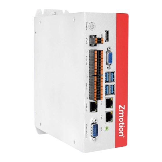
VPLC710 Motion Controller Hardware Manual V1.0 1.4. Production Appearance Appearance Description: Name Numbers Details Audio interface Output audio LAN1 Net port 1, can be configured as EtherCAT LAN2 Net port 2, can be configured as EtherCAT USB3.0 USB3.0... -
Page 10: Specification Parameter
VPLC710 Motion Controller Hardware Manual V1.0 USB3.0 USB3.0 VGA display interface HDMI HDMI display interface RS485 / RS232 RS485 (port1) & RS232 (port0) EtherCAT EtherCAT Bus interface Digital inputs Digital outputs 24V power supply Power inputs Reset button ON / OFF button 1.5. -
Page 11: Config Parameter Specification
VPLC710 Motion Controller Hardware Manual V1.0 Support SERVO_PERIOD to check Controller Period 1ms by default and adjust period VR Save Size when Ferroelectric memory stores power 2048 Power Off failure data for about 10 years heat-dissipating Cooling fin method Storage -40℃-80℃... - Page 12 VPLC710 Motion Controller Hardware Manual V1.0 Parameter Description: Item Default Specification Details Total memory, including all memories that can save data, such as, array Total Memory 256MB space, Zar file size, channel size, hmi resolution, etc., it is better to set the value that is above 200.
-
Page 13: Io Interface Specification
VPLC710 Motion Controller Hardware Manual V1.0 Task num Max tasks can be executed Array Space 25600000KB Distributed array space Zvobj num 2048 The number of vision object Avobject Sub num 4096 Max sub functions Com num Serial ports The number of PORT net-port, set value Eth num should be less than the max value Ethcustom num... -
Page 14: Communication Interface Specification
VPLC710 Motion Controller Hardware Manual V1.0 Pulse output Reuse output, number is OUT8-15. IO needs to be supplied by external power IO power input 24V DC input independently. 1.5.4. Communication Interface Specification Item Specification Details Standard 1000M Ethernet interface RJ45, it can be Communication configured as EtherCAT. -
Page 15: Interface Definition
EtherCAT interface are all standard interfaces, which can be connected and used through standard wiring cables. 1.6.2. RS485/RS232 VPLC710 series support RS485 protocol local IO communication and RS232 protocol local debug. Before use, it needs to configure the number of "com num" and related parameters on the "Config Window"... -
Page 16: Input & Output
VPLC710 Motion Controller Hardware Manual V1.0 Serial port communication specification: Item RS232 (port0) RS485 (port1) Maximum 115200(bps) 115200(bps) Communication Rate Terminal Resistor Topological Structure 1 to 1 Daisy Chain Topology The number of nodes can be extended The longer communication The longer communication distance is, the lower distance is, the lower... - Page 17 VPLC710 Motion Controller Hardware Manual V1.0 IO terminal definition form: Signal Description Note E24V External power 24V input IO Power terminal EGND External power ground OUT0 Output 0, PWM0 OUT1 Output 1, PWM1 OUT2 Output 2, PWM2 1. Outputs all are high-speed OUT3 Output 3, PWM3 outputs,...
- Page 18 VPLC710 Motion Controller Hardware Manual V1.0 IN12 Input 12 IN13 Input 13 IN14 Input 14 IN15 Input 15 Only 24V encoders can be used, and the pulse input frequency of encoder 0 and encoder 1 is up to 500kHz, which can be connected to high-speed encoders, the others are ordinary inputs, and the pulse input frequency is up to 10kHz.
-
Page 19: Power Supply
VPLC710 Motion Controller Hardware Manual V1.0 The voltage to open <15V Minimal current 2.3mA Impedance 3.3KΩ Overcurrent protection Capacitive isolation Respond time Below 10ms →General Digital Input Specification Item Specification Channel 8 (OUT0-OUT15) Mode NPN type Voltage level DC24V (-15%~+20%) Current to input (typical value) 4.8mA The voltage to open... -
Page 20: Chapter Ii System Configuration
VPLC710 Motion Controller Hardware Manual V1.0 Chapter II System Configuration 2.1. Connection Configuration External equipment & Software configuration: 1. Wired mouse and keyboard. 2. Displayer. 3. WIN10 operation system (technical version), ZDevelop development platform, all kinds of operation systems of machine tool industries. Note: ZDevelop development platform can be downloaded from our website, or contact us. -
Page 21: System Framework
Support power failure detection. 2.3. System Framework The VPLC710 series enters the general machine tool in the form of an industrial computer. The specific application requires an external displayer for display, a keyboard and mouse for interaction, an IO module is for general IO input and output functions, and an EtherCAT bus is to connect the servo drive and remote IO modules. - Page 22 VPLC710 Motion Controller Hardware Manual V1.0...
-
Page 23: Chapter Iii Wiring Reference
VPLC710 Motion Controller Hardware Manual V1.0 Chapter III Wiring Reference 3.1. Basic Requirements 3.1.1. Cable Requirements 1. The network cable adopts Category 5e STP, and the crystal head has a metal shell to reduce interference and to prevent information from being eavesdropped. 2. -
Page 24: Cable-Arrangment Requirements
VPLC710 Motion Controller Hardware Manual V1.0 3.1.2. Cable-Arrangment Requirements 1. Signal lines and power lines should be routed separately, try to adjust the position of controllers and drivers in the cabinet, and distribute signal lines and power lines in different areas. 2. -
Page 25: Wiring Requirements
VPLC710 Motion Controller Hardware Manual V1.0 3.1.3. Wiring Requirements 1. The cable that is with shield should connect two sides of shield layer to GND. 2. Power that supplies the power should connect to the grounding cable. 3.2. Terminal Wiring... -
Page 26: General Input Wiring
VPLC710 Motion Controller Hardware Manual V1.0 3.2.1. General Input Wiring 3.2.2. General Output Wiring 3.2.3. Wiring: Input as Encoder VPLC710 has two 24V single-ended encoder inputs on board. This example uses IN4-6 to connect the encoder for illustration. After the wiring is completed and configured with ATYPE(1)=3, IN4 is EA1, IN5 is EB1, IN6 is EZ1, and the corresponding encoder axis number is 1. -
Page 27: Wiring: Output Ad Pwm
VPLC710 Motion Controller Hardware Manual V1.0 3.2.4. Wiring: Output ad PWM Pay attention to select the OUT ports that support PWM function, OUT0~OUT3. 3.2.5. Wiring: Output as Pulse VPLC710 has 4 single-ended pulse outputs on board. This example uses OUT8 and OUT9 to connect the driver to illustrate. After OUT8 and OUT9 are configured with ATYPE(3)=1, OUT8 is DIR3, OUT9 is PUL3, and the corresponding pulse driver axis number is 3. -
Page 28: Wiring: Rs485
VPLC710 Motion Controller Hardware Manual V1.0 3.2.6. Wiring: RS485 485A is connected to 485A, 485B is connected to 485B, shield layer is connected to external shell. -
Page 29: Chapter Iv Installment Wiring
VPLC710 Motion Controller Hardware Manual V1.0 Chapter IV Installment Wiring 4.1. Installment Environment Ambient temperature: The ambient temperature has a great influence on the life of ➢ the controller, and the operating environment temperature of the controller is not allowed to exceed the allowable temperature range (0° C to 55° C). Install the controller vertically on the surface of the flame-retardant object in the ➢... -
Page 30: Installment Size
VPLC710 Motion Controller Hardware Manual V1.0 4.2. Installment Size 4.3. Installment Method Secure the controller to the mounting surface with two M5 screws. When installing, please pay attention to the installation position. Please face the front of the controller (the actual installation surface of the operator) to the operator and make it perpendicular to the wall. - Page 31 VPLC710 Motion Controller Hardware Manual V1.0 Due to the large power consumption and volume of this product, in order to facilitate ventilation and heat dissipation and easy module replacement, a corresponding distance should be reserved between the upper and lower parts of the module and the building and surrounding components, as shown in the figure:...
-
Page 32: Chapter V Maintain & Problem Processing
VPLC710 Motion Controller Hardware Manual V1.0 Chapter V Maintain & Problem Processing 5.1. Maintain Regularly Please regularly check the places that are difficult to check during operation. Always keep the controller in a clean state, effectively remove the dust on the surface of the product, and prevent the dust from entering the product, especially metal dust. -
Page 33: Common Problems
VPLC710 Motion Controller Hardware Manual V1.0 whether terminal 2. Replace damaged and corroded screws are loose. control cables. Check whether insulation of the control cable is cracked. 5.2. Common Problems Problems Suggestions Check whether the ATYPE of the controller is correct. ➢... - Page 34 VPLC710 Motion Controller Hardware Manual V1.0 Check whether IO power is needed. The output does not work. Check whether the output number matches the ID of the IO board. Check whether IO power supply is normal. ➢ Check whether signal electricity level is matched ➢...
Need help?
Do you have a question about the VPLC710 Series and is the answer not in the manual?
Questions and answers