Table of Contents
Advertisement
Quick Links
Advertisement
Table of Contents

Subscribe to Our Youtube Channel
Related Manuals for Zmotion XPLC3264E


Summary of Contents for Zmotion XPLC3264E
- Page 1 XPLC3264E Controller Hardware Manual Version 1.1...
- Page 2 XPLC3264E Controller Manual Copyright statement The copyright of this manual belongs to Shenzhen Zhengshen Technology Co., Ltd. Without the written permission of Zhengshen, no one can reprint, translate and copy any content in this manual. Refer to the ZBASIC software manual for detailed information about the ZMC controller software and the introduction and routines of each instruction.
- Page 3 XPLC3264E Controller Manual machine! Please be sure to design an effective safety protection device in the machine, and add an error handling program to the software, otherwise the loss caused by the company is not obliged or liable.
-
Page 4: Table Of Contents
XPLC3264E Controller Manual table of Contents XPLC3264E Controller Hardware Manual 1 ........Chapter One Introduction 1 ............ 1.1 Connection configuration 1 ..........1.2 Installation and programming 2 ........1.3 Product Features 2 ............ Chapter two Hardware description 3 ..........2.1 XPLC3264E Model specification 3 ........ -
Page 5: Chapter One Introduction
XPLC3264E Controller Manual Chapter One Introduction ZMC is short for ZMotion motion controller. ZMotion motion controller can be used in various occasions where offline or online operation is required. ZMC supports up to 12-axis linear interpolation, arbitrary circular interpolation, spatial circular, helical interpolation, electronic cam, electronic gear, synchronous following, virtual axis setting, etc. -
Page 6: Installation And Programming
Builder, C #, and other software. When debugging, you can connect ZDevelop software to the controller at the same time, and the dynamic library zmotion.dll is needed when the program runs XPLC programming can use ZBasic language and ladder diagram, and multiple programs can run simultaneously.The ladder... - Page 7 XPLC3264E Controller Manual mode. ● Maximum output pulse frequency of each axis 500kHz ● by Can be expanded up to 512 isolated input or output ports. CAN bus, ● Axis positive / negative limit signal port / origin signal port can be configured as any input port at will.
-
Page 9: Xplc3264E Model Specification
● A variety of program encryption means to protect customers' intellectual property rights. Chapter two Hardware description This article XPLC3264E is the general name of XPLC1664E / XPLC2464E and other controllers. All the controllers of this series have the same wiring and size. - Page 10 XPLC3264E Controller Manual number Array space 160000 160000 160000 VR number 1024 1024 1024 Program space 2MByte 2MByte 2MByte Flash space 128MByte (1000 128MByte (1000 8MByte (128 blocks) blocks) blocks) power input 24V DC input, IO24V 24V DC input, IO24V...
-
Page 11: Xplc3264E4
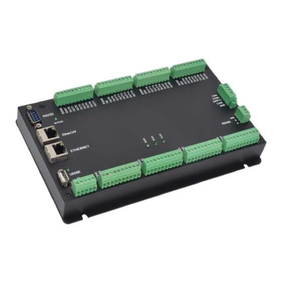
(common for pulse and output. Common for encoder and input). XPLC3264E has one RS232 serial port, one RS485, one network port, and one U disk interface. XPLC3264E has a CAN bus interface, which supports the connection of expansion modules... - Page 12 XPLC3264E Controller Manual (0-10V).
-
Page 13: Power / Can Interface Signal
XPLC3264E Controller Manual 2.2.1 Power / CAN interface signal: name Explanation number Internal power ground CANL CAN differential data EARTH / Safety ground / SHIELD shield CANH CAN differential data + + 24V Internal power supply 24V input Please separate the internal power supply 24V and external IO power supply 24V,... - Page 14 XPLC3264E Controller Manual name Explanation number Receive data pin Send data pin Power ground DC5V 5V power supply output, can be used to power the text screen...
-
Page 15: Rs485 Interface Signal
XPLC3264E Controller Manual To connect with the computer, you need to use a cross cable with a double female head. The touch screen and teaching box that need 24V power supply cannot be taken from here Electricity. 2.2.3 RS485 interface signal:... - Page 16 XPLC3264E Controller Manual Input 0 and input 1 have the function of latching input A and latching input B at the same time.
-
Page 17: Input 24-31 / Encoder Signal
XPLC3264E Controller Manual 2.2.4.2 Enter 8-15: name Explanation number EGND IO power ground EGND IO power ground Enter 8 Enter 8 Enter 9 Enter 9 Enter 10 Enter 10 Enter 11 Enter 11 Enter 12 Enter 12 Enter 13 Enter 13... - Page 18 XPLC3264E Controller Manual ground EGND IO power ground IN24 Enter 24 IN25 Enter 25 IN26 Enter 26...
-
Page 19: Output 1-2 / Io Power Signal
XPLC3264E Controller Manual IN27 Enter 27 IN28 Enter 28 IN29 Enter 29 IN30 Enter 30 IN31 Enter 31 Only 24V encoders can be used. 2.2.5 Output 1-2 / IO power signal: Output circuit name Explanation number EGND IO power ground... - Page 20 XPLC3264E Controller Manual OUT11 Output 11...
-
Page 21: Output 3-4 / Axis Pulse Signal
XPLC3264E Controller Manual OUT12 Output 12 OUT13 Output 13 OUT14 Output 14 OUT15 Output 15 Please separate the internal power supply 24V and external IO power supply 24V, especially in the case of severe electromagnetic interference on site. 2.2.6 Output 3-4 / axis pulse signal... - Page 22 XPLC3264E Controller Manual output 29 OUT30 500MA high current DIR0 output 30 OUT31 500MA high current PUL0 output 31 The pulse port can use E5V common anode output or E24V common anode output. Configure virtual axis for the corresponding axis (...
-
Page 23: Adda Signal
XPLC3264E Controller Manual 2.2.7 Wiring The ordinary output port is used as a pulse port, so it is an external power supply. Some drives are For 24V interface, OPTO can be directly connected to 24V. Single-ended connection Single-ended wiring reference with Panasonic A5... -
Page 24: Third Chapter Expansion Module
Analog port GND AIN0 0-10V analog input port 0 AIN1 0-10V analog input 1 XPLC3264E internal ADDA uses internal power supply. third chapter Expansion module Please refer to "ZIO Expansion Card Hardware Manual" Expansion moduleCAN bus, input and output, power... - Page 25 XPLC3264E Controller Manual CANH at the end.
-
Page 26: Chapter Four Faq
XPLC3264E Controller Manual Chapter Four common problem prob Suggestions for solving problems Confirm that the ATYPE configuration of the controller is correct; The motor does not rotate. Confirm whether the pulse sending mode and the input pulse mode of the driver match; Confirm whether there is hardware limit, software limit, and ALM signal function;... - Page 27 XPLC3264E Controller Manual The expansion module cannot Check whether the 120 ohm resistor is installed at be connected, the expansion both ends; module Check if there are multiple expansion modules with The warning light is on. the same ID. No signal detected at input Check whether the IO power supply is available;...
-
Page 28: Chapter Five Hardware Installation
XPLC3264E Controller Manual chapter Five Hardware installation Unit: mm mounting hole diameter 4.5mm total height of the controller 45mm...
Need help?
Do you have a question about the XPLC3264E and is the answer not in the manual?
Questions and answers