Table of Contents
Advertisement
Quick Links
Advertisement
Table of Contents

Related Manuals for THORLABS PDXR1


Summary of Contents for THORLABS PDXR1
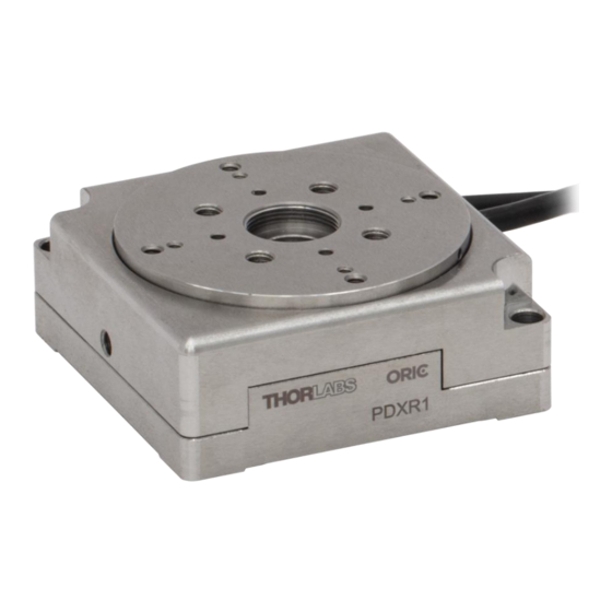
- Page 1 PDXR1(/M) Piezo Inertia Drive Rotation Stage with Optical Encoder User Guide...
-
Page 2: Table Of Contents
PDXR1(/M) Piezo Inertia Drive Rotation Stage with Optical Encoder Table of Contents Chapter 1 Safety ......................... 1 Chapter 2 Overview ........................3 Chapter 3 Installation ......................... 5 3.1.1 Mounting Features .............................. 5 3.1.2 Mounting on a Base ............................6 3.1.3 Post Mounting .............................. -
Page 3: Chapter 1 Safety
PDXR1(/M) Piezo Inertia Drive Rotation Stage with Optical Encoder Chapter 1: Safety Chapter 1 Safety Safety Information For the continuing safety of the operators of this equipment, and the protection of the equipment itself, the operator should take note of the Warnings, Cautions, and Notes throughout this manual and, where visible, on the product itself. - Page 4 PDXR1(/M) Piezo Inertia Drive Rotation Stage with Optical Encoder Chapter 1: Safety General Warnings Warning If this equipment is used in a manner not specified by the manufacturer, the protection provided by the equipment may be impaired. In particular, excessive moisture and/or dust may impair operation.
-
Page 5: Chapter 2 Overview
Overview Introduction The PDXR1(/M) stage features a piezo inertia motor that uses friction and inertia to translate the platform in discrete cycles. Each cycle consists of a relatively slow piezo expansion step accompanied by a rapid piezo contraction step. During the expansion step, the moving platform moves in the same direction as the piezo element due to friction, while the rapid piezo contraction causes the moving platform to slip and remain immobile due to inertia. - Page 6 The bottom surface features five #8 (M4) counterbores, providing a convenient means of attaching a load to the stage. PD1U(/M) mount on rotation platform of PDXR1(/M) via 2 pieces of M2(2-56) tapping holes in diagonal direction of rotation platform.
-
Page 7: Chapter 3 Installation
Take care to securely mount the stage before attaching components to the stage’s rotation platform. Mount the PDXR1(/M) stage on an even surface. The recommended flatness of the surface is ≤5 μm. For applications with large temperature variations, only mount the PDXR1(/M) stage on a surface that has the same or similar thermal expansion properties as the stage. -
Page 8: Mounting On A Base
3.1.2 Mounting on a Base The PDXR1 and PDXR1/M stages can mounted onto the MSB34 & MSB7510/M high-density optical breadboards, respectively. The breadboard provides a flat surface for mounting the stage and four 1/4" (M6) counterbored holes for mounting to an optical table or standard breadboard. -
Page 9: Post Mounting
PDXR1(/M) Piezo Inertia Drive Rotation Stage with Optical Encoder Chapter 3: Installation 3.1.3 Post Mounting The stage can be mounted vertically on a Ø1/2" post via the 8-32 (M4 x 0.7) tapped hole on the side opposite the cable exit. -
Page 10: Setting Up An Xy + Rotation Stage Configuration
Setting Up an XY + Rotation Stage Configuration This section describes how to build an XY + rotation stage using two PDX1(/M) linear stages and a PDXR1(/M) rotation stage. Note that the PDX1(/M) stages will need to be translated to access the mounting holes, which can be done using a PDXC controller. -
Page 11: Mounting Components To The Stage
PDXR1(/M) Piezo Inertia Drive Rotation Stage with Optical Encoder Chapter 3: Installation 3.1.5 Mounting Components to the Stage Caution Do not exceed the load capacity specified in Chapter 6. The load’s center of mass should be over the platform. Do not use screws and dowel pins that protrude past the maximum hole depth. - Page 12 Thorlabs offers a thin mounting adapter plate, PD1T(/M), to provide a convenient means of attaching a load to the PDXR1(/M) stage by a central 8-32 (M4 x 0.7) threaded hole and other 4-40 (M2 x 0.4 & M3 x 0.5) threaded holes.
- Page 13 PDXR1(/M) Piezo Inertia Drive Rotation Stage with Optical Encoder Chapter 3: Installation Thorlabs also offers the thick PD1U(/M) mounting adapter plate which provides a convenient means of attaching a load to the PDXR1(/M) stages using five #8 (M4) counterbores, as shown below: 1.
- Page 14 Before driving the PDXR1(/M) stage, the configuration of the PDXC controller must be set correctly. The controller can drive components using SMC and D-Sub connectors. The PDXR1(/M) stage only works in D-Sub mode and in either open- or closed-loop mode. Users can toggle between these two modes using the knob on the front panel of the controller during controller startup.
-
Page 15: Chapter 4 Operation
Confirm the configuration of the PDXC controller prior to use. Since the controller can drive both PD Series stages with SMC connectors and PDXR1(/M) stages with D-Sub connector respectively, the wrong configuration will not drive the stage properly and there is a risk of damage to the stage and/or the controller. - Page 16 Periodic maintenance helps to ensure the optimum stepping performance during its life span. Note The PDXR1(/M) stage is assembled with rust preventative oil. Do not wipe the stage with organic solvents. When necessary, clean the surfaces of the stage with a dry, dust-free cloth.
-
Page 17: Chapter 5 Software Reference
PDXR1(/M) Piezo Inertia Drive Rotation Stage with Optical Encoder Chapter 5: Software reference Chapter 5 Software reference GUI settings in D-Sub mode 5.1.1 GUI Setting in Open-Loop Mode In this mode, the main window of the GUI is as shown below. There is no home function in the open-loop mode. -
Page 18: Chapter 6 Specifications
PDXR1(/M) Piezo Inertia Drive Rotation Stage with Optical Encoder Chapter 6: Specifications Chapter 6 Specifications Item # PDXR1(/M) Travel Range 360° Continuous Optical Encoder Resolution 0.4365 µrad (0.09 arcsec) Minimum Incremental Motion 0.873 µrad (0.18 arcsec) Step Size, PDXC Only 0.01 to 999.0°... -
Page 19: Chapter 7 Frequently Asked Questions
50% or more over time. What driver can I use? The PDXR1(/M) stage must be driven by a Thorlabs PDXC controller with a firmware revision of 1.3.1 or higher. What is the maximum length of cable? The stages are shipped with 1.5 m (4.9 ft) of cable. -
Page 20: Chapter 8 Mechanical Drawings
PDXR1(/M) Piezo Inertia Drive Rotation Stage with Optical Encoder Chapter 8: Mechanical Drawings Chapter 8 Mechanical Drawings Figure 11 PDXR1 Imperial Stage Drawing Page 18 CTN020719-D02... - Page 21 PDXR1(/M) Piezo Inertia Drive Rotation Stage with Optical Encoder Chapter 8: Mechanical Drawings Figure 12 PDXR1/M Metric Stage Drawing Rev. A, June 21, 2023 Page 19...
-
Page 22: Chapter 9 Regulatory
Waste Treatment is Your Own Responsibility If you do not return an “end of life” unit to Thorlabs, you must hand it to a company specialized in waste recovery. Do not dispose of the unit in a litter bin or at a public waste disposal site. -
Page 23: Chapter 10 Declarations Of Conformity
PDXR1(/M) Piezo Inertia Drive Rotation Stage with Optical Encoder Chapter 10: Declarations of Conformity Chapter 10 Declarations of Conformity Rev. A, June 21, 2023 Page 21... -
Page 24: Chapter 11 Thorlabs Worldwide Contacts
PDXR1(/M) Piezo Inertia Drive Rotation Stage with Optical Encoder Chapter 11: Thorlabs Worldwide Contacts Chapter 11 Thorlabs Worldwide Contacts For technical support or sales inquiries, please visit us at for our most up-to-date www.thorlabs.com/contact contact information. USA, Canada, and South America UK and Ireland Thorlabs, Inc. - Page 25 www.thorlabs.com...
Need help?
Do you have a question about the PDXR1 and is the answer not in the manual?
Questions and answers