
Related Manuals for Amazone ZA-X


Summary of Contents for Amazone ZA-X
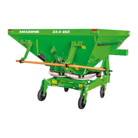
- Page 1 Operating Manual ZA-X 603 ZA-X 903 ZA-X 1403 ZA-XW 503 Fertiliser spreaders Please read this operating manual before first MG7693 commissioning. BAG0235.4 01.23 Keep it in a safe place Printed in Germany for future use. en_US...
- Page 2 Only in this way could you be satisfied both with the machine and with yourself. This goal is the purpose of this instruction manual. Leipzig-Plagwitz 1872. ZA-X BAG0235.4 01.23...
- Page 3 + 49 (0)5405 501-0 E-mail: amazone@amazone.de Spare part orders Spare parts lists are freely accessible in the spare parts portal at www.amazone.de. Please send orders to your AMAZONE dealer. Formalities of the operating manual Document number: MG7693 Compilation date: 01.23 ...
- Page 4 Dear Reader, We update our operating manuals regularly. Your suggestions for improvement help us to create ever more user-friendly manuals. AMAZONEN-WERKE H. DREYER SE & Co. KG Postfach 51 D-49202 Hasbergen Tel.: + 49 (0)5405 501-0 E-mail: amazone@amazone.de ZA-X BAG0235.4 01.23...
-
Page 5: Table Of Contents
PTO shaft ..........................40 5.4.1 Coupling the PTO shaft ......................42 5.4.2 Uncoupling the PTO shaft ...................... 42 5.4.3 PTO shaft with friction clutch (optional) ................. 43 Hydraulic connections ......................44 5.5.1 Coupling the hydraulic hose lines ..................45 ZA-X BAG0235.4 01.23... - Page 6 10.2.1 Complete discharging......................104 10.3 Recommendation for working in headlands ................ 105 10.4 Notes for spreading slug pellets (e.g. Mesurol) ..............106 10.4.1 Spread rate check with the machine at a standstill ............. 107 Faults ......................109 ZA-X BAG0235.4 01.23...
- Page 7 Inspection criteria for hydraulic hose lines ................122 12.11.4 Installation and removal of hydraulic hose lines ..............123 12.12 Electric lighting system ......................124 12.13 Upper and lower link pins check ..................124 12.14 Hydraulic diagram ........................ 125 12.15 Bolt tightening torques ......................126 ZA-X BAG0235.4 01.23...
-
Page 8: User Information
Number items in diagrams Numbers in round bracket refer to items in diagrams. The first number refers to the diagram and the second number to the item in the figure. Example: (Fig. 3/6) Figure 3 • Item 6 • ZA-X BAG0235.4 01.23... -
Page 9: General Safety Instructions
If the user discovers that a function is not working properly, then they must eliminate this fault immediately. If this is not the task of the user or if the user does not possess the appropriate technical knowledge, then they should report this fault to their superior (operator). ZA-X BAG0235.4 01.23... - Page 10 • Independently-executed construction changes to the machine. Insufficient monitoring of machine parts which are subject to • wear. • Improperly executed repairs. • Disasters through the impact of foreign bodies and acts of God. ZA-X BAG0235.4 01.23...
-
Page 11: Representation Of Safety Symbols
Non-compliance with these instructions can cause faults on the machine or in the environment. NOTE Indicates handling tips and particularly useful information. These instructions will help you to use all the functions of your machine to the optimum. ZA-X BAG0235.4 01.23... -
Page 12: Organisational Measures
As well as all the safety information in this operating manual, comply with the general, national regulations pertaining to accident prevention and environmental protection. When driving on public roads and routes, then you should comply with the statutory road traffic regulations. ZA-X BAG0235.4 01.23... -
Page 13: User Training
The personnel of a specialist workshop shall possess the ap- propriate knowledge and suitable aids (tools, lifting and support equipment) for carrying out the maintenance and repair work on the machine in a way which is both appropriate and safe. ZA-X BAG0235.4 01.23... -
Page 14: Safety Measures In Normal Operation
Risk of contusions, cuts, dragging, catching or knocks from support parts. It is forbidden to: • Drill holes in the frame or on the running gear. Increase the size of existing holes on the frame or the running gear. • Weld support parts. • ZA-X BAG0235.4 01.23... -
Page 15: Spare And Wear Parts And Aids
Immediately replace any machine parts which are not in a perfect state. Only use AMAZONE spare and wear parts released by AMAZONEN- WERKE, so that the type approval remains valid according to the national and international regulations. The use of wear and spare parts from third parties does not guarantee that they have been con- structed in a way as to meet the requirements placed on them. -
Page 16: Warning Pictograms And Other Signs On The Machine
2. The consequence of non-compliance with the danger protection instructions. For example: causes serious injuries to fingers or hands. 3. Instructions for avoiding the danger. For example: only touch machine parts when they have come to a complete standstill. ZA-X BAG0235.4 01.23... -
Page 17: Positions Of Warning Pictograms And Other Labels
General safety instructions 2.13.1 Positions of warning pictograms and other labels Warning pictograms The following diagrams show the arrangement of the warning picto- grams on the machine. Fig. 1 Fig. 2 Fig. 3 Fig. 4 ZA-X BAG0235.4 01.23... - Page 18 Keep a sufficient safety distance from the • machine danger area. Ensure that bystanders maintain a sufficient • safety distance from the machine danger area as long as the tractor engine is run- ning. ZA-X BAG0235.4 01.23...
- Page 19 Ensure that all personnel maintain an ade- • quate safety distance from suspended loads or raised machine parts. MD 095 Read and follow the operating manual and safety information before starting up the machine! ZA-X BAG0235.4 01.23...
- Page 20 ο from the intended workstation. ο if you are outside of the stroke area between the tractor and the machine. MD 100 This symbol indicates anchorage points for fas- tening slinging gear when loading the machine. ZA-X BAG0235.4 01.23...
- Page 21 MD 116 This symbol indicates the required drive speed (540 rpm) and direction of rotation of the drive shaft on the machine side. MD 199 The maximum operating pressure of the hydrau- lic system is 210 bars. ZA-X BAG0235.4 01.23...
-
Page 22: Dangers If The Safety Information Is Not Observed
Besides the safety information in this operating manual, the national general workplace safety and accident prevention regulations are binding. Comply with the accident prevention instructions on the warning pic- tograms. When driving on public roads and routes, comply with the appropriate statutory road traffic regulations. ZA-X BAG0235.4 01.23... -
Page 23: Safety Information For Users
Secure the operating lever of the tractor hydraulic system so that • unintentional raising or lowering is impossible, before connecting the machine to or disconnecting the machine from the tractor's three-point hydraulic system. ZA-X BAG0235.4 01.23... - Page 24 Before leaving the tractor, secure it from unintentionally starting • up or rolling away. For this: Lower the machine onto the ground ο ο Apply the parking brake ο Switch off the tractor engine Remove the ignition key ο ZA-X BAG0235.4 01.23...
- Page 25 Adjust your driving speed to the prevailing conditions. • Before driving downhill, switch to a low gear. • Before moving off, always switch off the independent wheel • braking (lock the pedals). ZA-X BAG0235.4 01.23...
-
Page 26: Hydraulic System
Replace the hydraulic hose line if it is damaged or worn. Use • only original AMAZONE hydraulic hose lines! • The hydraulic hose lines should not be used for longer than six years, including any storage time of maximum two years. Even... -
Page 27: Electrical System
Secure the PTO shaft guard by attaching the chain(s) to prevent • movement. • Observe the prescribed pipe overlaps in transport and opera- tional positions. (Read and follow the operating manual from the PTO shaft manufacturer.) ZA-X BAG0235.4 01.23... - Page 28 • universal joint shaft stub. • When using the travel-dependent universal joint shaft, note that the universal joint shaft speed depends on the drive speed, and that the direction of rotation reverses when you drive in reverse. ZA-X BAG0235.4 01.23...
-
Page 29: Fertiliser Spreader Operation
• Spare parts must meet at least the specified technical require- ments of AMAZONEN-WERKE. This is ensured through the use of original AMAZONE spare parts. ZA-X BAG0235.4 01.23... -
Page 30: Loading And Unloading
This section: • Provides a comprehensive overview of the machine structure. • Provides the names of the individual modules and controls. Read this section when actually at the machine. This helps you to understand the machine better. ZA-X BAG0235.4 01.23... -
Page 31: Overview Of Subassemblies
(8) Quick emptying (not for ZA-XW 503 ) (3) Spreading discs (9) Tele Quick border spreading vanes in park- ing position (4) Setting lever for rate slider ZA-X 903 / ZA-X 1403 (10) Guard tube (5) Setting lever for rate slider ZA-X 603 / ZA-... -
Page 32: Safety And Protection Equipment
(1) Two-way control (2) Cable with connection for lighting (3) Hydraulic hose lines Fig. 8 Transportation equipment ZA-X: Fig. 9/... (1) Rear lights, brake lights and turn indicators (2) Licence plate holder with lighting required if the tractor lighting and licence →... -
Page 33: Intended Use
Product description Intended use The AMAZONE fertiliser spreader ZA-X / ZA-XW is designed exclusively for conventional agricultural applications • and is suitable for spreading dry, granuled, prilled and crystalline fertiliser, seed and slug pellets. is attached to the tractor's three-point hydraulic system and op- •... -
Page 34: Danger Areas And Danger Points
Rating plate Machine rating plate (1) Implement number (2) Vehicle identification number (3) Product (4) Permissible technical implement weight (5) Model year (6) Year of manufacture ZA-X BAG0235.4 01.23... -
Page 35: Technical Data
Product description Technical data ZA-X +S 250 ZA-X + S 350 + L 800 ZA-X +S 350 ZA-XW +S 200 1403 136 gal 190 gal 200 gal 265 gal 375 gal 310 gal 375 gal 110 gal 155 gal Hopper capacity... -
Page 36: Necessary Tractor Equipment
The workplace-related emission value (acoustic pressure level) is 74 dB(A), measured in operating condition at the ear of the tractor driver with the cabin closed. Measuring unit: OPTAC SLM 5. The noise level is primarily dependent on the vehicle used. ZA-X BAG0235.4 01.23... -
Page 37: Structure And Function
The following section provides information on the machine structure and the functions of the individual components. Function The AMAZONE ZA-X fertiliser spreader is equipped with two hopper tips and spreading discs (1) that are driven from the inside out in... -
Page 38: Guard And Function Screens In The Hopper (Protective Device)
ZA-X 603 and ZA-XW have a screwed-on guard screen. Fig. 14 ZA-X 903 and ZA-X 1403 have a foldable guard screen. Fig. 15/... (1) Guard and function screen (2) Handle with guard screen lock (3) Lock for opened guard screen Fig. -
Page 39: Guard Tube (Protective Device)
Guard tube (protective device) Serves as a bumper for the prevention of acci- dents when the spreading discs are in operation. Fig. 19/1: • for ZA-X 903 / 1403 Fig. 19 Fig. 20/1: for ZA-X 603 / ZA-XW • Fig. 20... -
Page 40: Pto Shaft
Have any damaged or missing parts of the PTO shaft replaced • immediately with OEM parts from the PTO shaft manufacturer. Note that only a specialist workshop may repair a PTO shaft. ZA-X BAG0235.4 01.23... - Page 41 PTO shaft. • Before switching on the universal joint shaft, read and follow the safety precautions for universal joint shaft operation in the chap- ter entitled "Safety information for the user", page 27. ZA-X BAG0235.4 01.23...
-
Page 42: Coupling The Pto Shaft
3. Secure the tractor and machine against unintentional starting and unintentional roll- ing away. 4. Pull the PTO shaft off of the universal joint shaft of the tractor. 5. Place the PTO shaft in the holder provided (Fig. 23/1). Fig. 23 ZA-X BAG0235.4 01.23... -
Page 43: Pto Shaft With Friction Clutch (Optional)
2. Unscrew the lock nuts (Fig. 25/3) in the connection fork from the friction clutch. Re- move the setscrew (Fig. 25/4). 3. Pry the connection fork off of the gearbox input shaft using a flat bar. ZA-X BAG0235.4 01.23... -
Page 44: Hydraulic Connections
Danger of infection from escaping hydraulic fluid at high pres- sure! When coupling and uncoupling the hydraulic hose lines, ensure that the hydraulic system is depressurised on both the machine and trac- tor sides. If you are injured by hydraulic fluid, contact a doctor immediately. ZA-X BAG0235.4 01.23... -
Page 45: Coupling The Hydraulic Hose Lines
2. Unlock the hydraulic connectors from the hydraulic sockets. 3. Protect the hydraulic connector and hydrau- lic socket against soiling using the dust pro- tection caps. 4. Place the hydraulic hose lines in the hose cabinet (Fig. 26). Fig. 26 ZA-X BAG0235.4 01.23... -
Page 46: Spreading Discs
The spreading discs and agitators are driven by the PTO shaft via the gearbox. Fig. 28 Agitator Depending on the specifications of the setting chart, the agitator heads (Fig. 29/1) in the hopper tips can be disengaged Fig. 29 ZA-X BAG0235.4 01.23... -
Page 47: Slider
Take the respective slider position required from the setting chart. The slider position is read from the scale (Fig. 31/2 Fig. 32/2). The sliders are closed using hydraulic cylinders and opened using tension springs. Fig. 31 Fig. 32 ZA-X BAG0235.4 01.23... -
Page 48: Two-Way Control
2. Actuate tractor control unit (relieve load). Desired slider opens. → Close slider on one side Both sliders are open, lever in Position B! 1. Move lever for remaining open slider to Position A. 2. Operate tractor control unit. Desired slider closes. → ZA-X BAG0235.4 01.23... -
Page 49: Three-Way Control (Optional)
5.10 Three-way control (optional) The three-way control is required for hydraulic individual slider actuation and using the Lim- iter X for tractors with only one single-acting hydraulic connection. Limiter X → Hose identification blue • Fig. 35 ZA-X BAG0235.4 01.23... -
Page 50: 3-Point Attachment Frame
Structure and function 5.11 3-point attachment frame The frame of the ZA-X is designed so that it meets the requirements and dimensions of 3- point attachment of Category II or I and II. ZA-X 903 /1403 Fig. 36/… (1) Upper coupling point with switchable upper... -
Page 51: Boundary Spreading/Side Spreading
5.12 Boundary spreading/side spreading Limiter X (optional) Only for ZA-X 903 and ZA-X 1403. If the first tramline is half the working width of the field edge, you can carry out border spreading via remote control using the Limiter X. -
Page 52: Calibration Kit (Optional)
The calibration kit is used to determine the slider position for the desired spread rate using a nom- ogram. Installing: 1. Remove the plastic plug (Fig. 41/1). 2. Mount the outlet chute (Fig. 42/1) using the fastening screws (Fig. 42/2). Fig. 41 Fig. 42 ZA-X BAG0235.4 01.23... -
Page 53: Transport And Parking Device (Removable, Optional)
(Fig. 45/2) in the central bore Remove after taking out safety splint. ο Fig. 45 When installing the rigid rollers ensure that the pin (Fig. 45/3) goes through the bore of the frame, thus holding the rollers in longitudinal direction. ZA-X BAG0235.4 01.23... -
Page 54: Coupling Device
Hopper cover (optional) The hopper cover guarantees dry product even in wet weather. Hopper cover swivelable The swivelable hopper cover is folded forwards for filling. ZA-X 903, 1403 (Fig. 48): • (1) Hand lever for opening and closing (2) Automatic lock CAUTION To open and close the cover, grasp the hand lever by the handle only. -
Page 55: Hopper Extensions (Optional)
Fig. 50: Narrow hopper extensions: • S200 for ZA-XW503 • S250 for ZA-X 603 • S350 for ZA-X 903 / 1403 Fig. 51: Wide hopper extensions: Fig. 50 L800 for ZA-X 903 • (See also on page 35.) Fig. 51... -
Page 56: Row Spreading Attachment For Specialised Crops
6,5 ft 13 ft 50/50 0/30 10 ft 20 ft 80/80 6/36 13 ft 26 ft 80/80 6/36 16 ft 32 ft 10 m 80/80 10/41 20 ft 40 ft 12 m 80/80 14/45 ZA-X BAG0235.4 01.23... - Page 57 2. In the setting chart, look for the desired spread rate in kg/ha in the columns for the working width ο the travel speed ο for the respective fertilizer. 3. Look for the shutter position in the same line to the left. ZA-X BAG0235.4 01.23...
- Page 58 652 522 435 435 348 290 391 313 261 326 261 217 762 609 508 508 406 338 457 365 304 381 305 254 579 463 386 521 417 348 439 348 290 585 468 390 387 380 325 Nominal quantity [kg/ha] ZA-X BAG0235.4 01.23...
- Page 59 Nominal quantity [kg/ha] To determine the slider position for spread rates or speeds not listed here, refer to the ZA-X setting chart. As an alternative to the setting chart, you can also determine the shutter position using the calibration kit.
-
Page 60: Setting Chart
0032 (0) 3 821 08 52 0047 63 94 06 57 0030 22620 25915 0031 316369111 0046 46 259200 0061 3 9369 1188 00352 23637200 00372 50 62 246 0064 (0) 272467506 0081 (0) 3 5604 7644 ZA-X BAG0235.4 01.23... - Page 61 → Fertiliser Service for the • please refer to most up-to-date version of the setting chart, the AMAZONE Fertiliser Service will assist you over the tele- • phone in assigning the fertilisers and setting recommendations. +49 (0) 54 05 / 501 111 please consult the contact partner in your country.
-
Page 62: Easycheck (Option)
Afterwards, the collection mats are photographed using the smartphone. The app checks the lat- eral distribution using the photos. If necessary, changes to the settings are sug- gested. Use the AMAZONE Website to download the following: EasyCheck app • EasyCheck operating manual •... -
Page 63: Commissioning
Check that the scales on the spreading discs are installed correctly. The scales with values from 0 to 20 are assigned to the shorter spreading vanes and the scales with values from 30 to 50 are as- signed to the longer spreading vanes. ZA-X BAG0235.4 01.23... -
Page 64: Checking The Suitability Of The Tractor
§ 70 of the German Regulations Authorising the Use of Vehicles for Road Traffic and the required approval according to § 29, paragraph 3 of the Ger- man Road Traffic Regulations. ZA-X BAG0235.4 01.23... - Page 65 [m] Distance between the center of the lower See technical data of implement link connection point and the center of gravity of the rear-mounted implement or rear ballast (center of gravity distance) ZA-X BAG0235.4 01.23...
- Page 66 (Section 6.1.1.7). 6.1.1.6 Tire load capacity Enter the double value (two tires) of the approved load capacity (see, for example, tire manufacturer's documentation) in the table (Section 6.1.1.7). ZA-X BAG0235.4 01.23...
- Page 67 (GV), you must use ballast weights in addition to the front- mounted implement. If you do not achieve the minimum ballast at the rear ο (GH min) from the weight of the rear-mounted implement (GH), you must use ballast weights in addition to the rear- mounted implement. ZA-X BAG0235.4 01.23...
-
Page 68: Adjusting The Length Of The Pto Shaft To The Tractor
PTO shaft. Only actuate the operator controls for the tractor's three-point hydrau- lic system from the intended workstation. • if you are outside of the danger area between the tractor and the • machine. ZA-X BAG0235.4 01.23... - Page 69 8. Grease the universal joint shaft of the tractor and the gearbox input shaft before connecting the PTO shaft. The tractor symbol on the protective tube of the PTO shaft identi- fies the tractor-side connection of the PTO shaft. ZA-X BAG0235.4 01.23...
-
Page 70: Securing The Tractor / Machine Against Unintentional Start-Up And Rolling
4. Apply the tractor's parking brake. 5. Secure the machine against unintentional rolling (only attached machine) On flat ground using the parking brake (if available) or ο wheel chocks. On uneven ground or slopes using the parking brake and ο wheel chock. ZA-X BAG0235.4 01.23... -
Page 71: Coupling And Uncoupling The Machine
Instruct people to leave the danger area between the tractor and the machine before you approach the machine. Any helpers may only act as guides standing next to the tractor and the machine, and may only move between the vehicles when both are at a standstill. ZA-X BAG0235.4 01.23... - Page 72 WARNING If the lower link pins have one-sided bearings or are welded in, use ball sleeves with socket and integrated lynch pin. Risk of accident when disconnecting the machine from the trac- tor! ZA-X BAG0235.4 01.23...
- Page 73 → The upper link hooks lock automatically. 7. Perform a visual inspection to ensure that the upper and lower link hooks are correctly locked before reversing the tractor. ZA-X BAG0235.4 01.23...
-
Page 74: Uncoupling The Machine
2.7 Secure the tractor and machine against unintentional start- ing and unintentional rolling away. 2.8 Decouple the PTO shaft. 2.9 Place the PTO shaft in the holder provided. 2.10 Uncouple the supply lines. 2.11 Fasten the supply lines in the corresponding parking sock- ets. ZA-X BAG0235.4 01.23... -
Page 75: Adjustments
(this applies particularly for mixed fertilisers) or the active sub- stance distribution (e.g., for slug pellets or lime). Claims for damages not caused by the centrifugal spreader itself are excluded. ZA-X BAG0235.4 01.23... -
Page 76: Adjusting The Mounting Height
For dense crops (rapeseed), set the centrifugal broadcaster with the specified mounting height (e.g. 80/80) above the crop. If the growth height makes this impossible, configure according to the specifica- tions for late top dressing. ZA-X BAG0235.4 01.23... -
Page 77: Late Topdressing
Mounting height for late top dressing: Using the tractor's three-point hydraulic system, set the mounting height of the spreader so that the distance between the grain tips and the spreading discs is approx. 2 in / 5 cm (Fig. 59). Fig. 59 ZA-X BAG0235.4 01.23... -
Page 78: Setting The Spread Rate
Fig. 60 setting levers (Fig. 60/4) to this scale value. 5. Retighten the thumb nuts (Fig. 60/1). ZA-X 603, ZA-XW 503: 1. Close the sliders hydraulically. 2. Unscrew the clamping lever (Fig. 61/2). 3. On the scale (Fig. 61/1), locate the scale... -
Page 79: Setting The Spread Rate According To The Setting Chart
17 17,5 18,5 19,5 20,5 21,5 22,5 23,5 24,5 25,5 27,5 30 Tabel 1 Example: Working width: 40 ft [12 m] Working speed: 5 mph [8 km/h] Desired spread rate: 310 lb/ac [350 kg/ha] Read off shutter position: 16 → ZA-X BAG0235.4 01.23... -
Page 80: Determining The Slider Position Using The Calibration Kit (Optional)
[kg] (amount collected). (3) The coloured scale in the middle with the shutter position (position). Symbols on the calculator disc rule: Spread rate Spread rate collected Fig. 63 Shutter position ZA-X BAG0235.4 01.23... - Page 81 40 ft (12 m) from the chart (Fig. 65) of the nomogram or the rear side of the rear side of the calculator disc rule. Fig. 64 Fig. 65 Fig. 66 Symbols on the calculator disc rule: Working width ft [m] Calibration distance ft ZA-X BAG0235.4 01.23...
- Page 82 [kg] collected and com- pare with position K of the coloured scale. 9. Look for the desired spread rate 232 lb/ac (260 kg/ha) (B) on the scale and read-off the shutter position 12.8 (C) required. Fig. 69 ZA-X BAG0235.4 01.23...
-
Page 83: Setting The Working Width
After setting the working width, always check whether you have man- ually retightened the wing nut of the quick-release screw connection. ZA-X BAG0235.4 01.23... -
Page 84: Adjusting The Spreading Vane Positions
When spreading mixed fertilisers, note the following: • Each variety may have different flight characteristics. ο The individual varieties may separate. ο The recommended settings specified for lateral distribution • (working width) pertain solely to weight distribution, not to nutri- ent supply. ZA-X BAG0235.4 01.23... - Page 85 4.5 Firmly retighten the respective wing nut by hand (without a tool). Excerpt from the setting chart Name of the fertiliser 0,15 in 0,04 lb/in 3.72 mm 1, kg/ kg/l Example: 39 ft / 12 m Working width: 5 (short vane) 38 (long vane). → Vane position: ZA-X BAG0235.4 01.23...
-
Page 86: Checking The Working Width Using The Mobile Fertiliser Test Rig (Optional)
We recommend checking the set working width of the centrifugal broadcaster using the mobile fertiliser test rig. For more information, refer to the operating manual for the "mobile test rig". Fig. 71 ZA-X BAG0235.4 01.23... -
Page 87: Boundary, Ditch And Side Spreading
The fertiliser distribution in towards the centre of the field is still close to the nominal quantity. A small amount of fertiliser is thrown across the Fig. 74 field boundary. ZA-X BAG0235.4 01.23... -
Page 88: Boundary Spreading With Limiter X (Optional)
The values of the setting chart are to be understood as guide num- bers, as the fertiliser conditions may vary. Readjust the Limiter X if necessary. Excerpt from the setting chart Name of the fertiliser 0,15 in 0,04 lb/in 3.72 mm 1, kg/ kg/l ZA-X BAG0235.4 01.23... - Page 89 Working width Border spreading Boundary spreading Ditch spreading If necessary, perform boundary spreading with reduced spreading disc speed ( ) / PTO shaft speed ( PTO shaft speed at 450 rpm = spreading disc speed 600 rpm ZA-X BAG0235.4 01.23...
- Page 90 1. Set the Limiter X according to the setting chart. 2. Lower the Limiter X hydraulically (move it into operational posi- tion). 3. Carry out boundary/side spreading. 4. Raise the Limiter X hydraulically (take it out of operation). ZA-X BAG0235.4 01.23...
-
Page 91: Boundary And Side Spreading With The Tele-Quick Border Spreading Vane
8.5.3 Setting and installing the Tele-Quick border spreading vane Excerpt from the setting chart Name of the fertiliser 0,15 in 0,04 lb/in 3.72 mm 1, kg/ kg/l Working width Border spreading Boundary spreading Ditch spreading ZA-X BAG0235.4 01.23... - Page 92 (Fig. 79/2). 4. Set the read-off edge (Fig. 79/3) to the letter of the scale (Fig. 79/4) according to the set- ting chart and retighten the screw connec- tion. Fig. 79 ZA-X BAG0235.4 01.23...
- Page 93 (Fig. 81/1) on the left side of the machine back by two scale intervals (Fig. 81/2). When finished boundary spreading, return the left slider back to its original position and replace the spreading vanes. Fig. 81 ZA-X BAG0235.4 01.23...
-
Page 94: Boundary Spreading With Border Spread Deflector (Optional)
3. Swing the border spread deflector (Fig. 82/3) down from inoperative position to op- erating position (Fig. 83). 4. Tighten the winged nut (Fig. 82/2). Fig. 82 5. Switch off the left agitator head (refer to on page 95). Fig. 83 ZA-X BAG0235.4 01.23... -
Page 95: Switching The Agitator Head On And Off
84/3), when moving in the direction of rotation, does so ahead of the short vane (Fig. 84/4). Fig. 84 Otherwise the clip pin does not lock correctly in its end position. Fit clip pin only as shown. ZA-X BAG0235.4 01.23... -
Page 96: Transportation
During road transport, only lift the centrifugal broadcaster until • the top edge of the reflector is no more than 59 in / 1500 mm above the road surface. Secure the machine against unintentional lowering before driv- • ing on the road! ZA-X BAG0235.4 01.23... - Page 97 5 t. CAUTION Release of fertiliser during road transport due to unintended opening of the sliders. Before transportation, close both levers of the two-way control. ZA-X BAG0235.4 01.23...
-
Page 98: Use Of The Machine
Maintain a sufficient safety clearance between you and the driv- en PTO shaft. Direct people out of the danger area of the driven PTO shaft. • Shut down the tractor engine immediately in case of danger. • ZA-X BAG0235.4 01.23... - Page 99 When spreading mixed fertilisers, note the following: • Each variety may have different flight characteristics. ο The individual varieties may separate. ο • After ever use, remove any fertiliser clinging to the spreading vanes. ZA-X BAG0235.4 01.23...
-
Page 100: Filling The Centrifugal Broadcaster
Observe the permitted payload of the spreader (see technical • data) and axle loads of the tractor. • Fill the hopper only when the sliders are closed. CAUTION It is mandatory to observe the safety instructions from the ferti- liser manufacturer. ZA-X BAG0235.4 01.23... -
Page 101: Spreading Operation
Drive in such a way that you always have full control over the tractor with the attached machine. In so doing, take your personal abilities into account, as well as the road, traffic, visibility and weather conditions, the driving characteris- tics of the driver and the connected machine. ZA-X BAG0235.4 01.23... - Page 102 Secure the tractor and the machine against unintentional start- up and rolling before climbing onto the machine. WARNING Danger of being caught and drawn in with driven agitator! Never insert any objects through the guard and function screen while the tractor engine is running. ZA-X BAG0235.4 01.23...
- Page 103 If, despite an identical slider position, you determine that the two • hopper tips are not emptying uniformly, check the basic setting of the sliders. The service life of the spreading vanes depends on the kinds of • fertiliser used, the operating times and the spread rates. ZA-X BAG0235.4 01.23...
-
Page 104: Complete Discharging
Secure the tractor and the machine against unintentional start-up and rolling, before making adjustments to the machine. See Page 70. Not for ZA-XW. The ZA-X is equipped with 2 emptying flaps (Fig. 85/1). 1. Place a collecting bucket behind the re- spective hopper tip. -
Page 105: Recommendation For Working In Headlands
Using the method just described pre- vents fertiliser loss and over or under- fertilising and thus is an environmen- tally friendly way of working. ZA-X BAG0235.4 01.23... -
Page 106: Notes For Spreading Slug Pellets (E.g. Mesurol)
50 kg/ha, carry out a spread rate check with the machine at a standstill (see on page 107). Slug pellets must not be mixed with fertiliser or other materials • in an attempt to operate the spreader in a different setting range. ZA-X BAG0235.4 01.23... -
Page 107: Spread Rate Check With The Machine At A Standstill
2min. 30sec. 2min. 5sec. 1min. 47sec. 3min. 20sec. 2min. 30sec. 2min. 1min. 40sec. 1min. 26sec. 3min. 7.5sec. 2min. 21sec. 1min. 53sec. 1min. 34sec. 1min. 20sec. 2min. 47sec. 2min. 5sec. 1min., 40sec. 1min. 23sec. 1min. 11sec. Table 2 ZA-X BAG0235.4 01.23... - Page 108 Converting the time required to cover 0.5 ha at working widths/working speeds that are not listed in the table 5000 Required time [sec.] for covering 0.5 ha at the x 3.6 Working width ft [m] x work- desired working width ing speed mph [km/h] ZA-X BAG0235.4 01.23...
-
Page 109: Faults
Eliminate cause of bridging. uniformly at the identical slider position Basic settings of the sliders differ Check basic settings of the slid- ers. Spreading discs not rotating Shear bolt on the PTO shaft has Replace shear bolt. failed. ZA-X BAG0235.4 01.23... -
Page 110: Cleaning, Maintenance And Repairs
The set pressure of the high-pressure cleaner/steam jet ο must not exceed 120 bar. ο Comply with safety regulations when working with high pressure cleaners. ZA-X BAG0235.4 01.23... -
Page 111: Lubrication Instructions
Ratinax A PTO shaft For winter operation, grease the protective tubes to prevent them from freezing. Also observe the installation and service instruc- tions from the PTO shaft manufacturer, which are fastened to the PTO shaft. Fig. 88 ZA-X BAG0235.4 01.23... -
Page 112: Maintenance Plan - Overview
As necessary Maintenance work see page Component Workshop work • Replace Spreading vanes Check • Basic setting of sliders Check and replace if • Electric lighting system necessary Ventilate friction clutch PTO shaft with friction clutch • ZA-X BAG0235.4 01.23... -
Page 113: Removing The Pto Shaft
The fric- tion clutch is now ready to be used again. High humidity, large amounts of dirt or cleaning Fig. 91 the machine with high-pressure cleaners in- crease the likelihood of thermal distortion of the friction linings. ZA-X BAG0235.4 01.23... -
Page 114: Gearbox
The spreading vanes are made of especially wear-resistant • stainless steel. Nevertheless, we remind you that the spreading vanes and their swivel blades are wear parts. Replace the spreading vanes and / or swivel blades as soon as holes from abrasion are visible. ZA-X BAG0235.4 01.23... -
Page 115: Replacing The Spreading Vanes
The open side of the U-shaped spreading vane must be facing the direction of rotation. When exchanging the spreading vanes and swivel blades, use the assembly paste provided. This is the only way to ensure that the specified tightening torque is sufficient. ZA-X BAG0235.4 01.23... - Page 116 9. Swivel the read-off edge of each spreading vane until it reaches the setting required for the desired working width. 10. Firmly tighten the respective wing nut of the quick-release screw connection by hand (without using a tool). ZA-X BAG0235.4 01.23...
-
Page 117: Replacing The Swivel Blades
5.4 Tighten the self-locking nut with a tool so that the swivel blade can still just be swivelled by hand but cannot swing upwards automatically. ZA-X BAG0235.4 01.23... -
Page 118: Check The Clearances Between The Agitator Finger/Hopper Wall And Spreading Vane/Feed Plates
Do not reach into the outlet opening while operating the slider! Danger of crushing! Checking the basic settings of the sliders 1. Close the slider. 2. Set slider position 11 via the setting levers (Fig. 96/1). 3. Open the slider. Fig. 96 ZA-X BAG0235.4 01.23... - Page 119 The round steel must touch the shutter opening (4) and must not rest on the bottom plate (3)! 6. If the respective shutter opening is too small or too big, correct the basic shutter setting. ZA-X BAG0235.4 01.23...
- Page 120 7. Unscrew the lock nuts (Fig. 98/6) of the connecting rods (Fig. 98/5). 8. Twist the connecting rod until the stop (Fig. 98/3) rests against the setting lever (Fig. 98/2). 9. Retighten the lock nuts. Fig. 98 ZA-X BAG0235.4 01.23...
-
Page 121: Hydraulic System
Replace the hydraulic hose line if it is damaged or worn. Use • only original AMAZONE hydraulic hose lines! The hydraulic hose lines should not be used for longer than six • years, including any storage time of maximum two years. Even... -
Page 122: 12.11.1 Labelling Of Hydraulic Hose Lines
Movement of the hose out of the assembly. • Corrosion of assembly, reducing the function and tightness. • Installation requirements not complied with. • Life span of 6 years has been exceeded. • ZA-X BAG0235.4 01.23... -
Page 123: 12.11.4 Installation And Removal Of Hydraulic Hose Lines
12.11.4 Installation and removal of hydraulic hose lines When installing and removing hydraulic hose lines, always observe the following information: • Use only original AMAZONE hydraulic hose lines! • Ensure cleanliness. Always install the hydraulic hose lines to ensure the following in •... -
Page 124: Electric Lighting System
Visual check and measurements for wear. The permissible wear is 2 mm. Visual check for wear on the ball sleeves • If applicable: check the fastening bolts for tightness • If a wear criterion is met, replace the top link pin or lower link pin. ZA-X BAG0235.4 01.23... -
Page 125: Hydraulic Diagram
ο Right slider → Hose marking green Fig. 101 (1) Connection to control unit (2) 3-way control Left slider → Hose marking yellow ο Right slider → Hose marking green ο Limiter → Hose marking blue ο ZA-X BAG0235.4 01.23... -
Page 126: Bolt Tightening Torques
1180 [1600] 1660 [2250] 1991 [2700] ft lbs 15.2 [2.4] [4.9] [8,4] [20,6] [40,7] [70,5] [112] [174] [242] [342] [470] [589] Coated screws have different tightening torques. Note special information for tightening torques in chapter Mainte- nance ZA-X BAG0235.4 01.23...
Need help?
Do you have a question about the ZA-X and is the answer not in the manual?
Questions and answers