
Related Manuals for Amazone ZG-B 8200 Truck


Summary of Contents for Amazone ZG-B 8200 Truck
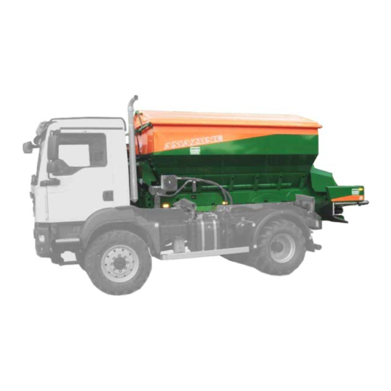
- Page 1 Operating Manual ZG-B 8200 Truck Pack top spreader Please read this operating manual before first commis- MG5979 sioning. BAG0170.2 02.21 Printed in Germany Keep it in a safe place for future use.
- Page 2 Reading the instruction Manual and following it should seem to be in- convenient and superfluous as it is not enough to hear from others and to realize that a machine is good, to buy it and to believe that now everything should work by itself.
- Page 3 + 49 (0)5405 501-0 E-mail: amazone@amazone.de Spare part orders Spare parts lists are freely accessible in the spare parts portal at www.amazone.de. Please send orders to your AMAZONE dealer. Formalities of the operating manual Document number: MG5979 Compilation date: 02.21 ...
- Page 4 We update our operating manuals regularly. Your suggestions for improvement help us to create ever more user-friendly manuals. AMAZONEN-WERKE H. DREYER GmbH & Co. KG Postfach 51 D-49202 Hasbergen Tel.: + 49 (0)5405 501-0 E-mail: amazone@amazone.de ZG- B BAG0170.2 02.21...
-
Page 5: Table Of Contents
Table of Contents User Information ..................8 Purpose of the document ......................8 Locations in the operating manual ................... 8 Diagrams used ......................... 8 General safety instructions ................. 9 Obligations and liability ......................9 Representation of safety symbols ..................11 Organisational measures ....................... - Page 6 Table of Contents Spreading granulated fertiliser with lime spreading discs ............. 46 Spreading of bone meal with bone meal spreading discs............. 47 Spreading disc holder ......................47 Boundary and side spreading with the boundary spreading Limiter ........48 5.10 Conveyor belt ........................48 5.10.1 Belt conveyor driven hydraulically ..................
- Page 7 Table of Contents 10.11 Screw tightening torques ....................... 95 Hydraulic diagram ..................96 ZG-B BAG0170.2 02.21...
-
Page 8: User Information
User Information User Information The User Information section provides information on use of the oper- ating manual. Purpose of the document This operating manual Describes the operation and maintenance of the machine. • Provides important information on safe and efficient handling of •... -
Page 9: General Safety Instructions
General safety instructions General safety instructions This section contains important information on safe operation of the machine. Obligations and liability Comply with the instructions in the operating manual Knowledge of the basic safety information and safety regulations is a basic requirement for safe handling and fault-free machine operation. Obligations of the operator The operator is obliged only to let those people work with/on the ma- chine who... - Page 10 General safety instructions Risks in handling the machine The machine has been constructed to the state-of-the art and the recognised rules of safety. However, there may be risks and re- strictions which occur when operating the machine For the health and safety of the operator or third persons, •...
-
Page 11: Representation Of Safety Symbols
General safety instructions Representation of safety symbols Safety instructions are indicated by the triangular safety symbol and the highlighted signal word. The signal word (danger, warning, cau- tion) describes the severity of the risk, and carries the following mean- ing: DANGER Indicates an immediate high risk which will result in death or serious physical injury (loss of body parts or long term damage) -
Page 12: Organisational Measures
General safety instructions Organisational measures The operator must provide the necessary personal protective equip- ment as per the information provided by the manufacturer of the crop protection agent to be used, such as: • Chemical-resistant gloves, • Chemical-resistant overalls, • Water-resistant footwear, •... -
Page 13: Operator Training
General safety instructions Operator training Only those people who have been trained and instructed may work with/on the machine. The operator must clearly specify the responsi- bilities of the people charged with operation and maintenance work. People being trained may only work with/on the machine under the supervision of an experienced person. -
Page 14: Danger From Residual Energy
General safety instructions Danger from residual energy Note that there may be residual mechanical, hydraulic, pneumatic and electrical/electronic energy on the machine. Use appropriate measures to inform the operating personnel. You can find detailed information in the relevant sections of this operating manual. -
Page 15: Spare And Wear Parts And Auxiliary Materials
Immediately replace any machine parts which are not in a perfect state. Only use AMAZONE spare and wear parts released by AMAZONEN- WERKE, so that the type approval remains valid according to the national and international regulations. The use of wear and spare parts from third parties does not guarantee that they have been con- structed in a way as to meet the requirements placed on them. -
Page 16: Warning Symbols And Other Labels On The Machine
General safety instructions 2.13 Warning symbols and other labels on the machine Always keep all the warning symbols on the machine clean and in a legible state. Replace illegible warning symbols. You can obtain the warning symbols from your dealer using the order number (e.g. MD 075). -
Page 17: Positions Of Warning Symbols And Other Labels
General safety instructions 2.13.1 Positions of warning symbols and other labels The following diagrams show the arrangement of the warning symbols on the machine. Fig. 1 Fig. 2 ZG-B BAG0170.2 02.21... - Page 18 General safety instructions Order number and explanation Warning symbols MD 075 Risk of fingers and hands being cut or cut off by accessible, moving parts involved in the work process. This danger can cause extremely serious injuries and the loss of body parts. •...
- Page 19 General safety instructions MD 088 Risk of being drawn in or caught by moving parts involved in the work process, caused by climbing on the loading platform when the machine is running. This danger can cause extremely serious and potentially fatal injuries. Never climb onto the loading platform when the tractor engine is running with PTO shaft / hydrau- lic / electronics system connected.
- Page 20 General safety instructions MD 098 Danger from flying fertiliser particles. Please ensure that all personnel maintain a suffi- cient safety distance and stay outside the danger area. MD 100 This symbol indicates anchorage points for fas- tening slinging gear when loading the machine. MD 114 This symbol indicates a lubrication point.
- Page 21 General safety instructions MD 174 Danger from unintended continued movement of the machine. Causes serious, potentially fatal injuries any- where on the body. Secure the machine against unintended contin- ued movement before uncoupling the machine from the tractor. To do this, use the parking brake and/or the wheel chock(s).
-
Page 22: Dangers If The Safety Information Is Not Observed
General safety instructions 2.14 Dangers if the safety information is not observed Non-compliance with the safety information • Can pose both a danger to people and also to the environment and machine. Can lead to the loss of all warranty claims. •... -
Page 23: Safety Information For The Operator
General safety instructions 2.16 Safety information for the operator 2.16.1 General safety and accident prevention information Beside these instructions, comply with the general valid national • safety and accident prevention regulations. • The warning symbols and labels attached to the machine pro- vide important information on safe machine operation. -
Page 24: Hydraulic System
• Replace the hydraulic hose line if it is damaged or worn. Only • use original AMAZONE hydraulic hose lines. The hydraulic hose lines should not be used for longer than six • years, including any storage time of maximum two years. Even... -
Page 25: Fertiliser Spreader Operation
General safety instructions 2.16.4 Fertiliser spreader operation Stay clear of the working area! Danger from flying fertiliser parti- • cles. Direct persons away from the throwing range of the fertilis- er spreader. Do not walk or stand close to rotating spreading discs. -
Page 26: Universal Joint Shaft Operation
● Spare parts must at least meet the specified technical require- ments of AMAZONEN-WERKE. This is ensured through the use of original AMAZONE spare parts. ZG- B BAG0170.2 02.21... -
Page 27: Mounting On A Carrier Vehicle
Mounting on a carrier vehicle Mounting on a carrier vehicle Loading with a lifting crane / mounting the spreader on the carrier ve- hicle Fig. 3 There are 2 attachment points respectively at the front (Fig. 3/1) and rear (Fig. 3/2) in the hopper. DANGER When loading the implement with a lifting crane, the marked at- tachment points for slings must be used. - Page 28 Mounting on a carrier vehicle 1. Lifting of the hopper using 4 attachment points. 2. Dismount the drawbar, jack and running gear (Fig. 4/1, 2, 3). 3. Mount the ZG TRUCK on the vehicle. 4. Couple the supply lines with the vehicle. ο...
-
Page 29: Mounting Dimensions
Mounting on a carrier vehicle Mounting dimensions ZG-B BAG0170.2 02.21... - Page 30 Mounting on a carrier vehicle (1) Mounting plates for M20 bolted connection. (2) Mounting straps for pins with 40 mm diameter ZG- B BAG0170.2 02.21...
-
Page 31: Required Hgv Equipment
Mounting on a carrier vehicle Required HGV equipment Electrical system Battery voltage: 12V (Volt) • Lighting socket: 7-pin • Hydraulic system Maximum operating pressure: • 210 bar Tractor pump capacity: • At least 40 l/min at 180 bar Implement hydraulic fluid: •... - Page 32 Mounting on a carrier vehicle Maximum permissible pressure in oil return: 8 bar Therefore do not connect the oil return to the control unit, but to a pressure-free oil return flow with a large plug coupling. WARNING For the oil return, use only DN16 lines and select short return paths.
-
Page 33: Product Description
Product description Product description Overview of subassemblies Fig. 5 (1) Frame (4) Guard tube (2) Belt conveyor (5) Spreader unit with spreading discs (3) Hopper (6) Gearbox (7) Swivelable hopper cover (Option) (8) Main shutter / Double shutter (Option) ZG-B BAG0170.2 02.21... -
Page 34: Safety And Protection Equipment
Product description Safety and protection equipment Guard tube Standard: Guard tube above the spreading disc. If the spreading disc is positioned at a height of 1500 mm, the guard tube must be installed underneath the spreading disc Fig. 6 Transportation equipment Fig. -
Page 35: Intended Use
Compliance with all the instructions in this operating manual. • Execution of inspection and maintenance work. • Exclusive use of original AMAZONE spare parts. Other uses to those specified above are forbidden and shall be con- sidered as improper. For any damage resulting from improper use: •... -
Page 36: Danger Areas
Product description Danger areas The danger area is the area around the machine in which people can be caught: By work movements made by the machine and its tools • By materials or foreign bodies thrown out of the machine •... -
Page 37: Technical Data
Product description Technical data Hopper size 8200 l Length over-all: 5292 mm Width 2260 mm Height 2240 mm Frame load capacity max. 12000 kg Standard speed 720 rpm Spreader disc speed Maximum permissible speed 870 rpm Standard speed depending on equipment Universal joint shaft Drive speed... -
Page 38: Structure And Function
The following section provides information on the machine structure and the functions of the individual components. Fig. 10 The AMAZONE ZG-B TRUCK bulk fertiliser spreader is a fertiliser spreader with hoppers from 8,200 l in volume. It is used for spreading damp fertiliser (spreading discs of lime) and •... -
Page 39: Main Shutter Slide
Structure and function Main shutter slide Fig. 11 (1) Main shutter slide (2) Hand lever for adjustment (3) Clamping bolt to secure adjustment (4) Scale (5) Pointer Adjust the quantity to be spread on the main shutter slide. Close the main shutter slide or double shutter during the transport. ZG-B BAG0170.2 02.21... -
Page 40: Double Shutter
Structure and function Double shutter Fig. 12 (1) Double shutter in operating position, both shutters closed (2) Spindle for commissioning the double shutter (3) R' clip (4) Attachment for 17 mm wrench Open and close hydraulically the fertilizer sluice via double shutter. By half side opening half side spreading is possible . -
Page 41: Fertiliser Chain Rake (Option)
Structure and function Fertiliser chain rake (option) Use the chain rake to spread lime and bone meal. The chain rake ensures even feed of the fertiliser to the spreading disc. 5.3.1 Chain rake, removable Assembly: insert the chain rake into the mount on the left and right side, and secure with a linch pin. - Page 42 Structure and function Take the chain rake out of operation (workshop task): 1. Put the chain hook in the parking device on the double shutter. 2. Put the double slider into operation. Fig. 16 ZG- B BAG0170.2 02.21...
-
Page 43: Spreading Granular Fertiliser With Spreading Discs Om
Structure and function Spreading granular fertiliser with spreading discs OM Fig. 17 (1) spreading discs OM (2) funnel chute For spreading granular fertilisers with the spreading discs OM always make use of the funnel chute. In this way the feed on point of the fertiliser on the spreading discs is optimised. - Page 44 Structure and function Setting the funnel chute Fig. 19 The holes are labelled with the numbers 1 and 2. Funnel chute position Spread rate Hole 1 up to 150 kg/ha Hole 2 More than 150 kg/ha ZG- B BAG0170.2 02.21...
-
Page 45: Spreading Lime With Lime Spreading Discs
Structure and function Spreading lime with lime spreading discs Fig. 20 (1) spreading discs of lime (2) guide plate For spreading earth-moist lime fertilizers, use the deflector guide and the chain rake. Setting the guide plate Fig. 21 ZG-B BAG0170.2 02.21... -
Page 46: Spreading Granulated Fertiliser With Lime Spreading Discs
Structure and function Spreading granulated fertiliser with lime spreading discs Fig. 22 (1) spreading discs of lime (2) guide plate Special case: For spreading granulated non-nitrogen fertiliser up to a working width of 18 m, use the roof chute. Roof chute assembly Fig. -
Page 47: Spreading Of Bone Meal With Bone Meal Spreading Discs
Structure and function Spreading of bone meal with bone meal spreading discs DANGER Risk of injury from colliding bone meal spreading vanes! Before using the bone meal spreading vanes, turn them by hand to make sure that the spreading vanes do not collide. Fig. -
Page 48: Boundary And Side Spreading With The Boundary Spreading Limiter
Structure and function Boundary and side spreading with the boundary spreading Limiter If the first tramline is half the working width of the field edge, you can carry out boundary spreading using the Limiter (Fig. 26). Shut down and turn on hydraulically the Limiter. -
Page 49: Belt Conveyor Driven Hydraulically
Structure and function 5.10.1 Belt conveyor driven hydraulically The belt conveyor is driven hydraulically by a gearbox. Fig. 28 5.11 Foldable ladder The foldable ladder (Fig. 29/1) enables a user to comfortably ascend the hopper for cleaning pur- poses. Warning Keep the ladder folded in and locked when the vehicle is in mo- tion (Fig. -
Page 50: Charging Sieves
Structure and function 5.12 Charging sieves For spreading • Granular fertiliser : Insert the sieve screen (Fig. 30/1) and secure using a lynch pin! Earth moist lime: remove the sieve screen. • Fig. 30 The charging sieves can be trodden on in order to clean the inside of the hopper. -
Page 51: Setting Chart
Through the FertiliserService application for Android and iOS mobile devices From the online FertiliserService • www.amazone.de → Service → FertiliserService Using the QR codes shown below, you can directly access the AMA- ZONE website to download the FertiliserService application. Android Contact partners in the respective countries: ... - Page 52 • spreading deflector If you cannot definitively assign the fertiliser to a kind listed in the setting chart the AMAZONE Fertiliser Service will assist you over the tele- • phone in assigning the fertilisers and setting recommendations +49 (0) 54 05 / 501 111 please consult the contact partner in your country •...
-
Page 53: Zg-B Drive
Structure and function 5.15 ZG-B Drive 5.15.1 AMATRON 3 in-cab terminal The AMATRON 3 in-cab terminal (Fig. 32) con- trols, operates and monitors the ZG-B Drive in a convenient manner. The spread rate is set electronically via adjust- ment the speed of the conveyer belt. The slider position required for a specific spreading quantity is determined by means of fertiliser calibration. -
Page 54: Control Block And Machine Computer
Structure and function 5.15.2 Control block and machine computer The valves of the hydraulic block are actuated via the AMATRON 3, thus ensuring all the hy- draulic functions. Depending on the equipment, the adjustable hydraulic throttles for the hydraulic swivelable hopper cover can be found on the hydraulic block. -
Page 55: Adjustments
Adjustments Adjustments When performing any adjustment work on the machine, observe the information in the following chapters "Warning symbols and other labels on the machine" from page • 16 and "Safety information for the operator" from page 23. • Observing this information is important for your safety. WARNING Danger of, shearing, cutting, entrapment, entanglement, being drawn in, caught or struck during all adjustment work on the... -
Page 56: Setting The Spread Rate
Adjustments Setting the spread rate Electro hydraulic spread rate setting via the floor belt speed. See the software AMABUS operating manual. The slider position depends on: the kind of fertiliser to be spread (quantity factor), • the working width, • the speed of operation . - Page 57 Adjustments Working witdh shutter position Belt speed km/h km/h km/h km/h km/h The value for the shutter position must be halved for the belt speed II. It is recommended to carry out a spread rate check with this slider position.
-
Page 58: Determining The Setting Value Using A Sliding Ruler
Adjustments 6.1.2 Determining the setting value using a sliding ruler The shutter position shown on the sliding ruler is valid for a forward speed of 10 km/h at a belt speed on gearbox position I. For other forward speeds, calculate the shutter position as fol- •... -
Page 59: Setting The Spread Rate Via The Main Shutter Slide
Adjustments 6.1.3 Setting the spread rate via the main shutter slide Fig. 35 1. Unscrew the locking bolt. 2. Move the main shutter to the desired value of the scale using the hand lever. 3. Tighten the locking bolt again. The setting figures of the setting chart may only be considered as standard data. -
Page 60: Spread Rate Control Mineral Fertiliser Calibration
Adjustments Spread rate control mineral fertiliser calibration Check the adjusted shutter slide positions by carrying out a calibration test using the calibration device (option). Spread rate control must be carried out: each time fertiliser is changed • • when spread rate is changed •... -
Page 61: Setting The Spreading Discs Om
Adjustments Setting the spreading discs OM 6.3.1 Setting the working width There are different spreading disc pairs for the various working • widths. • The existing tramline system (distance between the tramlines) determines the selection of the required spreading disc pair. The working widths are adjustable within the working ranges of •... -
Page 62: Adjusting The Spreading Vane Positions
Adjustments 6.3.2 Adjusting the spreading vane positions Fig. 37 The spreading vane position depends on: the working width and • the type of fertiliser. • Two different scales, designed so as to make it impossible to confuse them, are arranged on each spreading disc for precision setting of the individual spreading vane positions (Fig. - Page 63 Adjustments Adjust the spreading vanes as follows: 1. Turn off the spreading-disc drive. 2. Wait until rotating spreading discs come to a complete standstill before adjusting the working width. 3. Set the desired working width by swivelling the short and long spreading vanes in one after the other.
-
Page 64: Checking The Working Width With The Mobile Test Rig (Optional)
Adjustments 6.3.3 Checking the working width with the mobile test rig (optional) The working width is determined in part by the specific spreading properties of the fertiliser. As is well known, the primary factors that affect the spreading properties are: •... -
Page 65: Late Top Dressing
Adjustments 6.3.4 Late top dressing The spreading discs are supplied as standard with spreading vanes by which besides the nor- mal spreading (Fig. 39) procedure also late top dressing in crops may be conducted. For late top dressing Swivel the swivel blades of the spreading discs without slackening the nuts (without any tools) into the upper position (Fig. -
Page 66: Boundary, Ditch And Side Spreading
Adjustments Boundary, ditch and side spreading 1. Boundary spreading in accordance with fertiliser ordinance (Fig. 42) Along the field boundary there is a road, a field path or another person's lot. Fertiliser is not permitted to fall beyond the Fig. 42 boundaries in accordance with the fertiliser ordi- nance. -
Page 67: Boundary And Side Spreading Using The Limiter Zg-B Boundary Spread Deflector
Adjustments 6.4.1 Boundary and side spreading using the Limiter ZG-B boundary spread deflec- The setting of the Limiter M depends on Boundary distance • Type of fertiliser, • Nature of the field boundary • Read the value to be set from the setting chart. •... - Page 68 Adjustments Fig. 46/… (1) Boundary spreading deflector and scale with setting values from 0 to 15. (2) Display for the scale (3) Clamping lever (4) Guide bar (5) Position sensor Fig. 46 Lower the boundary spreading deflector hydraulically for border / •...
- Page 69 Adjustments Late top dressing with the Limiter For late top dressing bring the border spread deflector into a medium high position (Fig. 48). To do this lower the border spread deflector • hydraulically. On the upper side of the border spread deflector you will find on the right hand and left hand side each one setting lock (Fig.
-
Page 70: Transportation
Transportation Transportation WARNING Risk of crushing, shearing, cutting, being caught and/or drawn in, or impact when making interventions in the machine, through unintentional machine movements. Secure the machine against unintentional movements before • starting transportation. WARNING Danger of injury for persons standing in the vicinity of the ma- chine due to unintentional start-up of the implement! Switch-off the control terminal before road transport. -
Page 71: Use Of The Machine
Use of the machine Use of the machine When using the machine, observe the information in the following sections: "Warning symbols and other labels on the machine" from page • 16 and "Safety information for the operator", on page 23 ff. •... - Page 72 Use of the machine • For new machines, after 3-4 full hopper loads, check that the screws are tight and retighten if necessary. Use only fertiliser with the proper grain size, of the kinds listed in • the setting chart. If the type of fertiliser is not known exactly, check the working width using the mobile fertiliser test rig.
-
Page 73: Filling The Machine
Use of the machine Checking the outlet-openings of the guide chute before every operation Spreading material can build up inside the outlet openings (Fig. 50/1) of the guide chute to be- come too narrow to achieve a correct spread pattern. To achieve a correct spread pattern ensure that both outlets are clean. -
Page 74: Emptying The Machine While Stationary
Use of the machine Emptying the machine while stationary The ZG-B is emptied while stationary using the floor belt drive. For this: 1. Open the slide gate. 2. Remove the spreading discs. 3. Refit the spreading disc screws to protect the screw thread. 4. -
Page 75: Spreading Operation
Use of the machine Spreading operation Spreading disc OM • The spreading vanes and swivel blades are made of especially hard-wearing stainless steel. However, the spreading vanes and swivel blades are wearing parts. • The type of fertiliser, times of use and spread rates influence the service life of spreading vanes and swivel blades. - Page 76 Use of the machine See the software AMABUS operating manual. 1. Open the shutter. ο Main shutter: adjustment according to the setting chart. ο Double shutter: Open shutter hydraulically. 2. Engage the universal joint shaft at low tractor engine speed. 3.
-
Page 77: Recommendation For Working In Headlands
Use of the machine Recommendation for working in headlands Prerequisite for accurate work at field boundaries and edges. The first tramline (Fig. 51/T1) is gen- erally placed half a tramline's width from the edge of the field (see page 77). A tramline of this type is laid in the same fashion in the headlands. -
Page 78: Faults
Clean the spreading discs and uniform. ing discs and the spreading the spreading vanes. vanes. The spreading properties of your Contact the AMAZONE Fertiliser fertiliser differ from those of the Service. one we tested when creating the 05405-501 111 setting chart. - Page 79 Faults Fault Cause Remedy ZG-B Special, Super: Select gearbox position 1 or 2. Floor belt does not convey ferti- liser Idle gearbox. Bearing defective Replace the bearing. Collision of the PTO shaft and Unfavourable geometry on the Mount the drive unit offset: order flange of the towing eye.
-
Page 80: Cleaning, Maintenance And Repairs
Regular and proper maintenance is a requirement of our warran- ty conditions. Use only genuine AMAZONE spare parts (see "Spare and wear • parts and auxiliary materials" section, page 15). -
Page 81: Cleaning
Cleaning, maintenance and repairs 10.1 Cleaning Monitor brake, air and hydraulic hose lines particularly carefully. • • Never treat brake, air and hydraulic hose lines with benzene, benzole, petroleum or mineral oils. After cleaning, grease the machine, in particular after cleaning •... -
Page 82: Lubrication Point Overview
Cleaning, maintenance and repairs 10.2 Lubrication point overview Lubricate all the lubricating nipples (keep the seals clean). Lubricate / grease the machine at the specified intervals (operating hours h). The lubrication points on the machine are indi- cated with the film (Fig. 53). Carefully clean the lubrication points and grease gun before greasing, so that no dirt enters the bearing. -
Page 83: Maintenance Schedule - Overview
Cleaning, maintenance and repairs 10.3 Maintenance schedule – overview Carry out maintenance work when the first interval is • reached. The times, continuous services or maintenance intervals of • any third party documentation shall have priority. Daily Maintenance work Component Workshop work page Spreading discs and vanes... -
Page 84: Exchanging The Spreading Discs
Cleaning, maintenance and repairs 10.4 Exchanging the spreading discs Fig. 54 1. Remove the M10 hexagonal bolt (Fig. 54/1). 2. Pull off the spreading disc from the gearbox shaft. 3. Set up other spreading disc. 4. Fix spreading disc. When setting up spreading discs do not mix up "left hand" and "right hand". -
Page 85: Replacing The Spreading Vanes And Swivel Vanes
Cleaning, maintenance and repairs 10.5 Replacing the spreading vanes and swivel vanes • The technical condition of the spreading vanes, including their swivel blades, is essential for uniform lateral distribution of the fertiliser on the field (i.e. forming strips). The spreading vanes are made of especially wear-resistant •... - Page 86 Cleaning, maintenance and repairs Spreading vanes OM (1) Self-locking nut (2) Washer (3) Fixing bolt (4) Quick-release screw connection (5) Plate spring 1. Release and remove the fixing bolt. 2. Release and remove the quick-release screw connection. 3. Replace the spreading vane. 4.
-
Page 87: Replacing The Swivel Vanes Om
Cleaning, maintenance and repairs 10.5.2 Replacing the swivel vanes OM WARNING Danger of ejection of swivel blades of spreading vanes caused by the unintentional release of screw connections! When replacing the spreading blades, it is essential to replace used self-locking nuts of the screw connections with new ones. A used self- locking nut no longer has the required clamping force to produce a secure screw connection. -
Page 88: Belt Conveyor With Automatic Belt Control
The belt conveyor then runs outwards. One-sided belt conveyor running is prevented by the automatic belt control in AMAZONE bulk fertiliser spreaders ZG-B. The conveyor belt is tensioned in the floor belt... -
Page 89: Hydraulic System
Cleaning, maintenance and repairs 10.7 Hydraulic system WARNING Risk of infection through the high pressure hydraulic fluid of the hydraulic system entering the body! • Only a specialist workshop may carry out work on the hydraulic system. Depressurise the hydraulic system before carrying out work on •... -
Page 90: Labelling Hydraulic Hose Lines
• Replace the hydraulic hose line if it is damaged or worn. Only use original AMAZONE hydraulic hose lines. The hydraulic hose lines should not be used for longer than six • years, including any storage time of maximum two years. Even... -
Page 91: Maintenance Intervals
Cleaning, maintenance and repairs 10.7.2 Maintenance intervals After the first 10 operating hours, and then every 50 operat- • ing hours 1. Check all the components of the hydraulic system for tightness. 2. If necessary, tighten screw unions. Before each start-up: 1. -
Page 92: Installation And Removal Of Hydraulic Hose Lines
Cleaning, maintenance and repairs 10.7.4 Installation and removal of hydraulic hose lines • only genuine AMAZONE replacement hoses. These hoses stand up to chemical, mechanical and thermal loads. hose clips made from V2A for fitting hoses, as a rule. •... -
Page 93: Hydraulic Fluid Filter
Cleaning, maintenance and repairs 10.8 Hydraulic fluid filter The oil filter (Fehler! Verweisquelle konnte nicht gefunden werden./1) with its contamina- tion indicator (Fehler! Verweisquelle konnte nicht gefunden werden./2) monitors the contam- ination of the hydraulic oil. • Check the contamination indicator regularly to ensure proper function of the hydraulic system and its components. -
Page 94: Gearbox
Cleaning, maintenance and repairs 10.10 Gearbox Gear oil: 090 l SAE • There is no need to change the oil. • Fill levels: Conveyor belt gearbox with hydr. drive 1,0l ο Universal spreader unit gearbox 2,5l ο ZG- B BAG0170.2 02.21... - Page 95 Cleaning, maintenance and repairs 10.11 Screw tightening torques 10.9 12.9 M 8x1 M 10 16 (17) M 10x1 M 12 18 (19) M 12x1,5 M 14 M 14x1,5 M 16 M 16x1,5 M 18 M 18x1,5 M 20 M 20x1,5 M 22 M 22x1,5 1050...
- Page 96 Hydraulic diagram Hydraulic diagram 1. Control spool valve (P) red 2. Pressure free return flow (T) red 3. Oil filter 4. Inspection port 5. Load-Sensing- control cable (LS) red 6. System reversing screw 7. Hopper cover open 8. Double shutter right hand side (green) 9.
- Page 97 Hydraulic diagram ZG-B BAG0170.2 02.21...
Need help?
Do you have a question about the ZG-B 8200 Truck and is the answer not in the manual?
Questions and answers