Table of Contents
Advertisement
Quick Links
Advertisement
Table of Contents

Related Manuals for Amazone ZA-M Profis


Summary of Contents for Amazone ZA-M Profis
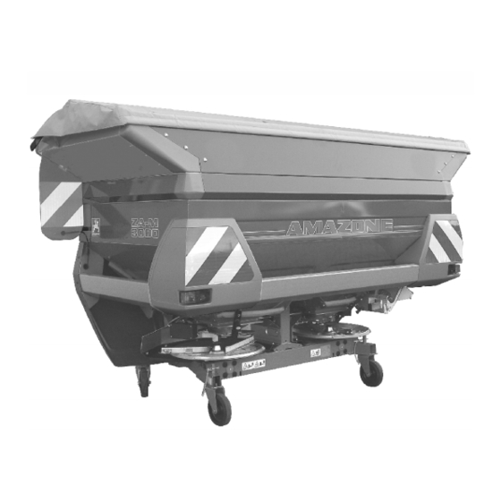
- Page 1 Operating Manual ZA-M Profis ZA-M Special Profis Fertiliser spreader with weighing technology Please read this operating manual before first MG3333 commissioning. BAG0039.8 03.12 Printed in Germany Keep it in a safe place for future use.
- Page 2 Reading the instruction Manual and following it should seem to be in- convenient and superfluous as it is not enough to hear from others and to realize that a machine is good, to buy it and to believe that now everything should work by itself.
- Page 3 + 49 (0)5405 501-234 E-mail: amazone@amazone.de Spare part orders Spare parts lists are freely accessible in the spare parts portal at www.amazone.de. Please send orders to your AMAZONE dealer. Formalities of the operating manual Document number: MG3333 Compilation date: 03.12 ©...
- Page 4 Send us your suggestions by fax. AMAZONEN-WERKE H. DREYER GmbH & Co. KG Postfach 51 D-49202 Hasbergen Tel.: + 49 (0)5405 501-0 Fax: + 49 (0)5405 501-234 E-mail: amazone@amazone.de ZA-M BAG0039.8 03.12...
-
Page 5: Table Of Contents
Table of Contents User Information ..................8 Purpose of the document......................8 Locations in the operating manual...................8 Diagrams used .........................8 General safety instructions.................9 Obligations and liability ......................9 Representation of safety symbols..................11 Organisational measures .......................12 Safety and protection equipment ...................12 Informal safety measures.......................12 User training...........................13 Safety measures in normal operation ..................14 Danger from residual energy ....................14... - Page 6 Table of Contents 5.8.1 Coupling the PTO shaft......................48 5.8.2 Uncoupling the PTO shaft ..................... 49 5.8.3 PTO shaft with friction clutch (optional)................. 50 Hydraulic system connections....................51 5.9.1 Coupling the hydraulic hose lines ..................52 5.9.2 Uncoupling the hydraulic hose lines..................52 5.10 Hyclick electro-hydraulic preselection ...................
- Page 7 Table of Contents 11.3 Faults, causes and remedies ....................103 11.4 Malfunctions, causes and remedies for Comfort equipment ..........104 Cleaning, maintenance and repairs............105 12.1 Cleaning ..........................106 12.2 Lubrication instructions ......................107 12.2.1 Lubricating the PTO shaft ....................107 12.3 Maintenance plan – Overview....................108 12.4 Shear-off safety devices for PTO shaft and agitator shaft drives ........109 12.5...
-
Page 8: User Information
User Information User Information The User Information section provides information on use of the oper- ating manual. Purpose of the document This operating manual • Describes the operation and maintenance of the machine. • Provides important information on safe and efficient handling of the machine. -
Page 9: General Safety Instructions
General safety instructions General safety instructions This section contains important information on safe operation of the machine. Obligations and liability Comply with the instructions in the operating manual Knowledge of the basic safety information and safety regulations is a basic requirement for safe handling and fault-free machine operation. Obligations of the operator The operator is obliged only to let those people work with/on the ma- chine who... - Page 10 General safety instructions Risks in handling the machine The machine has been constructed to the state-of-the art and the recognised rules of safety. However, there may be risks and restric- tions which occur when operating the machine • For the health and safety of the user or third persons, •...
-
Page 11: Representation Of Safety Symbols
General safety instructions Representation of safety symbols Safety instructions are indicated by the triangular safety symbol and the highlighted signal word. The signal word (DANGER, WARNING, CAUTION) describes the gravity of the risk and has the following sig- nificance: DANGER Identifies an immediate danger with a high risk that may cause death or serious physical injuries (loss of limbs or long-term damage) if not avoided. -
Page 12: Organisational Measures
General safety instructions Organisational measures The operator must provide the necessary personal protective equip- ment, such as: • Protective glasses • Protective shoes • Protective suit • Skin protection agents, etc. The operation manual • Must always be kept at the place at which the machine is oper- ated. -
Page 13: User Training
General safety instructions User training Only those people who have been trained and instructed may work with/on the machine. The operator must clearly specify the responsi- bilities of the people charged with operation, maintenance and repair work. People being trained may only work with/on the machine under the supervision of an experienced person. -
Page 14: Safety Measures In Normal Operation
General safety instructions Safety measures in normal operation Only operate the machine if all the safety and protection equipment is fully functional. Check the machine at least once a day for visible damage and check the function of the safety and protection equipment. Danger from residual energy Note that there may be residual mechanical, hydraulic, pneumatic and electrical/electronic energy on the machine. -
Page 15: Spare And Wear Parts And Aids
Immediately replace any machine parts which are not in a perfect state. Only use AMAZONE spare and wear parts released by AMAZONEN-WERKE, so that the type approval remains valid accord- ing to the national and international regulations. The use of wear and spare parts from third parties does not guarantee that they have been constructed in a way as to meet the requirements placed on them. -
Page 16: Warning Pictograms And Other Signs On The Machine
General safety instructions 2.13 Warning pictograms and other signs on the machine Always keep all the warning pictograms of the machine clean and in a legible state. Replace illegible warning pictograms. You can obtain the warning pictograms from your dealer using the order number (e.g. MD 075). -
Page 17: Positions Of Warning Pictograms And Other Labels
General safety instructions 2.13.1 Positions of warning pictograms and other labels Warning pictograms The following diagrams show the arrangement of the warning picto- grams on the machine. Fig. 1 Fig. 2 Fig. 3 Fig. 4 Fig. 5 ZA-M BAG0039.8 03.12... - Page 18 General safety instructions Order number and explanation Warning pictograms MD 075 Danger to fingers or hands from moving op- erating elements due to cutting or cutting off. In these cases there is a danger of extremely serious injuries leading to the loss of body parts such as fingers or hands.
- Page 19 General safety instructions Order number and explanation Warning pictograms MD 082 Danger of persons falling from tread surfaces and platforms when riding on the machine or when climbing on powered machines. This danger can cause extremely serious and potentially fatal injuries. It is forbidden to ride on the machine and/or climb on the machine when it is in operation.
- Page 20 General safety instructions Order number and explanation Warning pictograms MD 093 Danger due to catching or entrapment due to accessible powered elements of the machine. These dangers can cause extremely serious and potentially fatal injuries. Never open or remove protective devices from driven machinery •...
- Page 21 General safety instructions Order number and explanation Warning pictograms MD 097 Danger from crushing and impacts between the rear of the tractor and the machine during coupling/uncoupling. These dangers can cause extremely serious and potentially fatal injuries. • It is prohibited to operate the tractor's 3- point hydraulic system while persons are present between the rear of the tractor and the machine.
- Page 22 General safety instructions Order number and explanation Warning pictograms MD 106 Danger from crushing, shearing and/or im- pacts due to accidental movement of unse- cured machine parts. These dangers can cause extremely serious and potentially fatal injuries. Secure moving machine parts using the safety locking device to prevent accidental movement before entering the danger area.
-
Page 23: Dangers If The Safety Information Is Not Observed
General safety instructions 2.14 Dangers if the safety information is not observed Non-compliance with the safety information • Can pose both a danger to people and also to the environment and machine. • Can lead to the loss of all warranty claims. Seen individually, non-compliance with the safety information could pose the following risks: •... -
Page 24: Safety Information For Users
General safety instructions 2.16 Safety information for users WARNING Risk of contusions, cuts, dragging, catching or knocks from in- sufficient traffic and operational safety. Before starting up the machine and the tractor, always check their traffic and operational safety. 2.16.1 General safety and accident prevention information •... - Page 25 General safety instructions • When coupling and uncoupling machines, move the support equipment (if available) to the appropriate position (stability). • When actuating the support equipment, there is a danger of in- jury from contusion and cutting points! • Be particularly careful when coupling the machine to the tractor or uncoupling it from the tractor! There are contusion and cutting points in the area of the coupling point between the tractor and the machine.
- Page 26 General safety instructions Machine transportation • Comply with the national road traffic regulations when using public highways. • Before moving off, check: ο The correct connection of the supply lines ο The lighting system for damage, function and cleanliness ο The brake and hydraulic system for visible damage ο...
-
Page 27: Hydraulic System
General safety instructions 2.16.2 Hydraulic system • The hydraulic system is under a high pressure. • Ensure that the hydraulic hose lines are connected correctly. • When connecting the hydraulic hose lines, ensure that the hy- draulic system is depressurised on both the machine and tractor sides. -
Page 28: Electrical System
General safety instructions 2.16.3 Electrical system • When working on the electrical system, always disconnect the battery (negative terminal). • Only use the prescribed fuses. Using unsuitable fuses will de- stroy the electrical system - risk of fire. • Ensure that the battery is connected correctly - firstly connect the positive terminal and then connect the negative terminal. - Page 29 General safety instructions • When turning corners, observe the permitted bending and dis- placement of the PTO shaft. • Before switching on the universal joint shaft, check that the se- lected universal joint shaft speed of the tractor matches the per- mitted drive rev.
-
Page 30: Fertiliser Spreader Operation
• Spare parts must meet at least the specified technical require- ments of AMAZONEN-WERKE. This is ensured through the use of original AMAZONE spare parts. ZA-M BAG0039.8 03.12... -
Page 31: Loading And Unloading
Loading and unloading Loading and unloading WARNING Danger from crushing and / or impacts due to unintentional dropping of the raised machine! • It is essential to use the marked lashing points for securing load supporting devices if you are loading or unloading the machine with lifting gear. -
Page 32: Product Description
Product description Product description Overview of subassemblies Fig. 7 ZA-M BAG0039.8 03.12... -
Page 33: Safety And Protection Equipment
Product description Fig. 7/… (1) Frame (2) Hopper (3) Omnia-set spreading discs OM (4) Setting lever for manual spread rate setting (only for malfunc- tions) (5) Boundary spreading device Limiter (optional) (6) PTO shaft (7) Collection bucket for spread rate check without weighing tech- nology (8) Weighing frame (9) AMATRON... -
Page 34: Supply Lines Between The Tractor And The Machine
Product description Supply lines between the tractor and the machine ● Hydraulic hose lines ● Cable with connection for lighting ● Computer cable with machine connector Insertion positions for supply lines which are not in use: Fig. 8/… (1) Hose rack for hydraulic hose line (2) Parking position for lighting connection (3) Parking socket for machine connector Fig. -
Page 35: Intended Use
Product description Intended use The AMAZONE fertiliser spreader ZA-M Profis / Special Profis • is designed exclusively for conventional agricultural applications and are suitable for spreading dry, granuled, prilled and crystal- line fertiliser, seed and slug pellets. • is attached to the tractor's 3-point hydraulic system (Cat II) and operated by one person. -
Page 36: Rating Plate And Ce Marking
Product description The operating person may only move the machine or switch or drive the tools from the transport position to the working position or vice- versa when there is no-one in the machine danger area. Danger points exist: • Between the tractor and the machine, particularly during cou- pling and uncoupling operations. -
Page 37: Technical Data
3100 1,56 2,76 2,93 ZA-M 3001 Profis ZA-M Profis / Specal Profis Working width 10-36 (depending on spreading disc and type of fertiliser) 0.62 (Distance between the centre of the lower link ball and the centre of gravity of the rear implement) -
Page 38: Necessary Tractor Equipment
Product description Necessary tractor equipment For proper machine operation, the tractor must fulfil the following re- quirements: Tractor engine power Hopper capacity: 1000 l from 60 kW (82 bhp) upwards 1500 l from 65 kW (90 bhp) upwards 3000 l from 112 kW (150 bhp) upwards Electrical system Battery voltage:... -
Page 39: Structure And Function
The following section provides information on the machine structure and the functions of the individual components. Function Fig. 12 The AMAZONE ZA-M fertiliser spreader is equipped with two hopper tips and replaceable spreading discs (Fig. 12/1) that are driven from the inside out in opposite directions and counter to the direction of travel, and are equipped with one short (Fig. -
Page 40: Guard And Function Screens In The Hopper (Protective Device)
Structure and function Guard and function screens in the hopper (protective device) WARNING Danger of being caught and drawn in with driven agitator! • Never open the guard and function screen while the tractor en- gine is running. The foldable guard and function screens cover the entire hopper and serve •... -
Page 41: Spreading Discs
Structure and function Spreading discs As seen in the direction of travel: • Left spreading disc (Fig. 19/1) with L mark. • Right spreading disc (Fig. 19/2) with R mark. Spreading vane: • Long (Fig. 19/3) - Adjustment scale with values from 35 to 55. -
Page 42: Slide Gate And Dosing Slider
Structure and function Slide gate and dosing slider Fig. 22 Dosing slider The spread rate is set electronically with the on-board computer AMATRON In this case, dosing sliders (Fig. 22/2) operated by setting motors (Fig. 22/1) release a range of different diameters at the outlet open- ings (Fig. -
Page 43: Boundary, Ditch And Side Spreading
Structure and function Boundary, ditch and side spreading Limiter (optional, Fig. 24) If the first tramline is half the working width of the field edge, you can carry out boundary spreading via remote control using the Limiter M. Fig. 24 Hydraulic throttle (Fig. -
Page 44: Weighing Technology
Structure and function Weighing technology Fig. 28/... (1) Weighing frame (2) Weighing cell (3) Leaf spring (4) Bearing strap (5) Micrometer (6) Check screw The fertiliser spreader ZA-M makes it possible, with the aid of weighing technology, to determine exactly the fertiliser spread quantity. Likewise, an exact metering can be ensured without a calibration test. -
Page 45: Pto Shaft
Structure and function On the left and right of the frame of the fertiliser spreader ZA-M, there is a check screw set at 2 mm clearance to the weighing frame. These check screws prevent the spreader being raised from the weighing frame in event of ground undulations. - Page 46 Structure and function WARNING Danger of crushing from tractor and machine unintentionally starting up or rolling away! Couple or decouple the PTO shaft and tractor only when tractor and machine have been secured against both unintentional starting and unintentional rolling away. WARNING Danger of catching or entrapment due to the unprotected gear- box input shaft owing to the use of a PTO shaft with a short PTO...
- Page 47 Structure and function WARNING Danger from being entangled and drawn in by unguarded PTO shaft parts in the power transmission area between the tractor and driven machine! Work only when the drive between the tractor and driven machine is fully guarded. •...
-
Page 48: Coupling The Pto Shaft
Structure and function 5.8.1 Coupling the PTO shaft WARNING Danger from crushing or impact if there is insufficient clearance when coupling the PTO shaft! Couple the PTO shaft with the tractor before coupling the machine with the tractor. This will ensure the necessary clearance for safe coupling of the PTO shaft. -
Page 49: Uncoupling The Pto Shaft
Structure and function 5.8.2 Uncoupling the PTO shaft WARNING Danger from crushing or impact if there is insufficient clearance when uncoupling the PTO shaft! First uncouple the machine from the tractor before uncoupling the PTO shaft from the tractor. This will ensure the necessary clearance for safe uncoupling of the PTO shaft. -
Page 50: Pto Shaft With Friction Clutch (Optional)
Structure and function 5.8.3 PTO shaft with friction clutch (optional) The PTO shaft with friction coupling is recommended in the event of frequent shearing of the shear bolt between the connection fork and gearbox flange bush and for tractors with hard-mesh universal joint shaft coupling. -
Page 51: Hydraulic System Connections
Structure and function Hydraulic system connections WARNING Danger of infection from escaping hydraulic fluid at high pres- sure! When coupling and uncoupling the hydraulic hose lines, ensure that the hydraulic system is depressurised on both the machine and trac- tor sides. If you are injured by hydraulic fluid, contact a doctor immediately. -
Page 52: Coupling The Hydraulic Hose Lines
Structure and function 5.9.1 Coupling the hydraulic hose lines WARNING Danger from faulty hydraulic functions in event of incorrectly connected hydraulic hose lines! When coupling the hydraulic hose lines, observe the coloured mark- ings on the hydraulic plugs. Here, see "Hydraulic connections", page •... -
Page 53: Hyclick Electro-Hydraulic Preselection
Structure and function 5.10 Hyclick electro-hydraulic preselection The Hyclick is an electro-hydraulic preselection device for convenient operation of all hydraulic functions with only one double-acting tractor control unit. See Hyclick operating manual. • Preselection of left shutter L • Preselection of right shutter R •... -
Page 54: 3-Point Attachment Frame
Structure and function 5.11 3-point attachment frame The frame of the ZA-M is designed so that it meets the requirements and dimensions of 3- point attachment of Category II. Fig. 37/… (1) Bottom link pin with handle (2) Top link pin (3) Clip pin for securing lower link and top link pins. -
Page 55: Transport And Parking Device (Removable, Optional)
Structure and function 5.13 Transport and parking device (removable, optional) The removable transport and parking device enables easy coupling to the tractor's three-point linkage and easy manoeuvring in the yard and indoors. To prevent the fertiliser spreader from rolling, the 2 guide rollers are equipped with a locking sys- tem. -
Page 56: Swivelable Hopper Cover (Optional)
Structure and function 5.14 Swivelable hopper cover (optional) The swivelable hopper cover ensures that the product remains dry even in wet weather. During filling, the swivelable hopper cover is folded forwards using a hand lever. Swivelable hopper cover hydraulically actuated (optional, actuated via AMATRON , only in con- junction with Comfort equipment). -
Page 57: Two-Way Control (Optional)
Structure and function 5.16 Two-way control (optional) The two-way-control is necessary for hydraulic single slider actuation with • tractors with only a double-acting tractor control unit. A – Ball valve closed B – Ball valve open Half-side spreading with two-way control 1. - Page 58 Structure and function Boundary spreading with three-way control 1. Keep the two actuating levers for slide gates (Fig. 44) closed. 2. Open the actuating lever (Fig. 44) for Limiter. 3. Operate tractor control unit. → Lower Limiter. 4. Close the actuating lever (Fig. 44) for Limiter. 5.
-
Page 59: Commissioning
Commissioning Commissioning This section contains information • on commissioning your machine. • on checking how you may connect the machine to your tractor. • Before operating the machine for the first time the operator must have read and understood the operating manual. •... -
Page 60: Checking The Suitability Of The Tractor
Commissioning Checking the suitability of the tractor WARNING Danger of breaking during operation, insufficient stability and insufficient tractor steering and braking power on improper use of the tractor! • Check the suitability of your tractor, before connecting the ma- chine to the tractor. You may only connect the machine to tractors suitable for the purpose. - Page 61 Commissioning 6.1.1.1 Data required for the calculation Fig. 45 [kg] Empty tractor weight See tractor operating manual or vehicle [kg] Front axle load of the empty tractor documentation [kg] Rear axle load of the empty tractor [kg] Total weight of rear-mounted machine or See technical data for machine or rear bal- rear ballast last...
- Page 62 Commissioning 6.1.1.2 Calculation of the required minimum ballasting at the front G of the tractor to en- V min sure steering capability • − • • • Enter the numeric value for the calculated minimum ballast G V min required on the front side of the tractor, in the table (section 6.1.1.7). 6.1.1.3 Calculation of the actual front axle load of the tractor T V tat...
- Page 63 Commissioning 6.1.1.7 Table Actual value according to Approved value ac- Double approved calculation cording to tractor load capacity (two instruction manual tyres) Minimum ballast front / rear ≤ Total weight ≤ ≤ Front axle load ≤ ≤ Rear axle load •...
-
Page 64: Installing The Pto Shaft
Commissioning Installing the PTO shaft WARNING • Use only the PTO shaft prescribed by AMAZONE! • Install the PTO shaft only with the spreader detached and in an unloaded condition. WARNING Danger of catching or entrapment by the unprotected input shaft of... -
Page 65: Adjusting The Length Of The Pto Shaft To The Tractor
Commissioning 9. Fit the guard half (Fig. 49/1). 10. Turn the PTO shaft guard (Fig. 49/2) to the block position. 11. Screw in the locking screw (Fig. 49/3). Fig. 49 12. Assemble the PTO shaft. 13. Secure the PTO shaft guard against rota- tion by attaching the chain to the machine (Fig. - Page 66 Commissioning WARNING Danger of being caught and drawn in if the PTO shaft is installed incorrectly or if unauthorised design changes are made. Only a specialist workshop may make design changes to the PTO shaft. When doing so, read and follow the operating manual provided. Adjusting the length of the PTO shaft is permitted with consideration of the required minimum profile overlap.
-
Page 67: Securing The Tractor / Machine Against Unintentional Start-Up And Rolling
Commissioning 6. When measuring the length and shortening the PTO shaft, read and follow the operating manual from the PTO shaft manufac- turer. 7. Put the shortened halves of the PTO shaft back together. 8. Grease the universal joint shaft of the tractor and the gearbox input shaft before connecting the PTO shaft. -
Page 68: Setting The System Converting Bolt On The Spreader Valve Block
Commissioning Setting the system converting bolt on the spreader valve block Only for Comfort equipment! Fig. 51/... (1) System converting bolt (2) LS connection for the load sensing control line Fig. 52/... (1) Tractor connection for the load sensing control line (2) Tractor connection for the load sensing pressure hose (3) Tractor connection for the pressure-free... -
Page 69: Coupling And Uncoupling The Machine
Coupling and uncoupling the machine Coupling and uncoupling the machine When coupling and decoupling the machine, comply with the chapter "Safety information for the user", page 24. WARNING Danger from crushing, catching, entanglement and / impacts caused by unintentional starting and rolling of the tractor when the tractor's PTO shaft and supply lines are coupled or decoup- led! Secure the tractor and machine against unintentional start-up and... -
Page 70: Coupling The Machine
Coupling and uncoupling the machine Coupling the machine WARNING Danger from crushing and / or impacts when coupling the ma- chine between the tractor and the machine! Instruct people to leave the danger area between the tractor and the machine before you approach the machine. Any helpers may only act as guides standing next to the tractor and the machine, and may only move between the vehicles when both are at a standstill. - Page 71 Coupling and uncoupling the machine 1. Secure the machine to prevent it from accidentally rolling away if the machine is equipped with a transport fixture – see "Transport and parking device" chapter on page 55. 2. Always check for visible damage when coupling the machine: See the chapter "Obligation of operator"...
-
Page 72: Uncoupling The Machine
Coupling and uncoupling the machine Uncoupling the machine WARNING Danger from crushing and / or impacts • due to insufficient stability and tilting of the uncoupled ma- chine on uneven, soft ground! • due to unintentional rolling of the machine parked on a transportation device! •... -
Page 73: Adjustments
Secure the tractor cabin against entry of other persons to prevent unintentional actuation of the tractor's hydraulic system. Configure all settings of the AMAZONE ZA-M centrifugal broad- caster according to the information in the setting chart. All common kinds of fertiliser on the market are spread in the Ama- zone spreading hall, and the setting data measured during this pro- cess are incorporated into the setting chart. - Page 74 Service for the most up-to-date version of the setting chart, • the AMAZONE Fertiliser Service will assist you over the tele- phone in assigning the fertilisers and setting recommendations. +49 (0) 54 05 / 501 111 •...
-
Page 75: Adjusting The Mounting Height
Adjustments Adjusting the mounting height WARNING Danger of crushing and / or impact for persons behind / under the fertiliser spreader due to unintentional dropping of the fertil- iser spreader if the top link halves are accidentally rotated apart or tear apart! Make sure no persons are present in the danger area behind or be- low the machine before adjusting the mounting height via the upper link. -
Page 76: Setting Normal Fertilising/Late Top Dressing
Adjustments The mounting heights specified here in cm—usually horizontal 80/80—apply for normal fertilising. For spring fertilising, if the plants have already grown to a height of 10-40 cm, one-half of the growth height should be added to the speci- fied mounting height (e.g. 80/80). Therefore, for a growth height of 30 cm, set a mounting height of 95/95. -
Page 77: Setting The Spread Rate
Adjustments Mounting height for late top dressing: Using the tractor's three-point linkage, set the mounting height of the spreader so that the distance between the grain tips and the spread- ing discs is approx. 5 cm (Fig. 55). Fasten the lower link pins in the lower link connections at the bottom if required. -
Page 78: Spread Rate Check
Adjustments Spread rate check See AMATRON operating manual / Calibrating fertiliser section. Carry out spread rate check: • each time fertiliser is changed • when spread rate is changed • when working width is changed Alternatively, the spread rate check is: •... -
Page 79: Preparations For Spread Rate Check (Without Weighing Technology)
Adjustments 8.4.1 Preparations for spread rate check (without weighing technology) 1. Set the required slider position at the left hopper tip to achieve the desired spread rate. 2. Remove the two spreader discs. 2.1 Unscrew the thumb bolt (Fig. 59/1) se- curing the spreader disc and remove the spreader disc from the gearbox shaft. -
Page 80: Setting The Working Width
Adjustments Setting the working width • There are different spreading disc pairs for the various working widths. • The existing tramline system (distance between the tramlines) determines the selection of the required spreading disc pair. • The working widths are adjustable within the working ranges of the respective Omnia Set (OM) spreading disc pairs (however, there may be deviations for the spreading of urea). -
Page 81: Replacing The Spreading Discs
Adjustments 8.5.1 Replacing the spreading discs WARNING Danger from shearing, cutting or cutting off, catching or entan- glement and impacts by unintentional contact with moving oper- ating elements (spreading vanes of rotating spreading discs) during use of the machine without the necessary deflector. You must retrofit your fertiliser spreader with a deflector if you want to install spreading discs OM 24-36. -
Page 82: Adjusting The Spreading Vane Positions
Adjustments 8.5.2 Adjusting the spreading vane positions Fig. 62 The spreading vane position depends on: • the working width and • the type of fertiliser. Two different scales, designed so as to make it impossible to confuse them, are arranged on each spreading disc for precision setting of the individual spreading vane positions (Fig. - Page 83 Adjustments Adjust the spreading vanes as follows: 1. Switch off the tractor's universal joint shaft. 2. Secure the tractor against unintentional starting and rolling away, see the chapter "Securing the tractor against unintentional start- ing and rolling away", from page 67. 3.
-
Page 84: Checking The Working Width With The Mobile Test Rig (Optional)
Adjustments 8.5.3 Checking the working width with the mobile test rig (optional) The setting values of the setting chart are to be considered guideline values, as the spreading properties of the different types of fertiliser change. We recommend checking the set work- ing width of the throw spreader using the mobile fertiliser test rig (Fig. -
Page 85: Boundary, Ditch And Side Spreading
Adjustments Boundary, ditch and side spreading 1. Boundary spreading in accordance with fertiliser ordinance (Fig. 64): Along the field boundary there is a road, a field path or another person's lot. Fertiliser is not permitted to fall beyond the boundaries in accordance with the fertiliser ordi- Fig. -
Page 86: Boundary And Side Spreading Using The Limiter Boundary Spread Deflector
Adjustments 8.6.1 Boundary and side spreading using the Limiter boundary spread deflector The setting of the Limiter depends on • Boundary distance • Type of fertiliser, • Nature of the field boundary Read the value to be set from the setting chart (Fig. 67). •... - Page 87 Adjustments To set the values, position the boundary spread deflector on the guide bracket. 1. For this purpose, release the clamping lever (Fig. 68/1). If the turn range of the clamping lever is insuffi- cient, raise the handle, press it back and lower again.
-
Page 88: Boundary And Side Spreading Using The Tele-Set Boundary Spreading Disc
Adjustments 8.6.2 Boundary and side spreading using the Tele-Set boundary spreading disc For boundary spreading (as per fertiliser ordi- nance) and side spreading (beside your own areas to be treated in the same way), replace the left Omnia-Set spreading discs (left side spreading), viewed in direction of travel, with the appropriate boundary Tele-Set spreading disc. - Page 89 Adjustments Extract from setting chart YARA calcium ammonia nitrate 27% N + 4% MgO granular (80006352) Diameter 3.88 mm Bulk density: 1 kg/l Quantity factor 0,941 TS 5-9 TS 10-14 TS 15-18 TS 4 Disc 10 10,5 12 13,5 14 12 13,5 14 boundary margin [m]...
-
Page 90: Special Situations During Boundary Spreading (Where The Distance Between The Centre Of The Tramline And Field Edge Does Not Correspond To Half The Working Width)
Adjustments 8.6.3 Special situations during boundary spreading (where the distance between the centre of the tramline and field edge does not correspond to half the working width) In this case, the slider position (setting lever position) for the spread rate setting selected depends on the different working widths (dis- tances between the tramlines). -
Page 91: Notes On Om 10-12 And Om 10-16 Spreading Discs
Adjustments 8.6.4 Notes on OM 10-12 and OM 10-16 spreading discs With the 10-16, the throwing range W is approx. 36 m. This may be a disadvantage for boundary spreading: Working widths AB of 10 or 12 m, and of the first tramline at the field edge (use of boundary spread deflector), of a working width AB of 10 m, and of the first tramline of half the working width... -
Page 92: Transportation
Transportation Transportation • Comply with the chapter "Safety information for the user", from page 26 when moving. • Before moving off, check: ο The correct connection of the supply lines ο The lighting system for damage, function and cleanliness ο The hydraulic system for visible defects WARNING Risk of contusions, cutting, catching, drawing in and knocks... -
Page 93: Use Of The Machine
Use of the machine Use of the machine When using the machine, observe the information in the following sections: • "Warning pictograms and other signs on the machine" • "Safety information for the user", on page 24 ff. Observing this information is important for your safety. WARNING Danger from catching, entanglement, pulling in or entrapment due to accessible moving elements (e.g. - Page 94 Use of the machine WARNING Danger from being entangled and drawn in and danger from for- eign objects being caught and thrown in the danger area of the driven PTO shaft! • Whenever the machine is used, first check to ensure that the safety devices and guards of the PTO shaft are fully intact and functional.
-
Page 95: Filling The Centrifugal Broadcaster
Use of the machine 10.1 Filling the centrifugal broadcaster WARNING Danger of breaking during operation, insufficient stability and insufficient tractor steering and braking power on improper use of the tractor! Comply with the maximum load of the connected machine and the approved axle and support loads of the tractor. -
Page 96: Spreading Operation
Use of the machine 10.2 Spreading operation • The spreading vanes and swivel blades are made of especially hard-wearing stainless steel. However, the spreading vanes and swivel blades are wearing parts. • The type of fertiliser, times of use and spread rates influence the service life of spreading vanes and swivel blades. - Page 97 Use of the machine WARNING Risk of contusions, cutting, catching, drawing in and knocks through insufficient stability and tipping of the tractor and/or the connected machine. Drive in such a way that you always have full control over the tractor with the attached machine.
- Page 98 Use of the machine The fertiliser spreader is operated using the AMATRON See the AMATRON operating manual! • The fertiliser spreader is coupled to the tractor and the hydraulic hoses are connected. • The settings have been configured. 1. Couple the universal joint shaft at a low tractor engine speed. •...
-
Page 99: Recommendation For Working In Headlands
Use of the machine 10.2.1 Recommendation for working in headlands Correctly laid tramlines correctly is the prerequi- site for accurate work at field boundaries or edges. As a rule, when using the boundary spreading device Limiter or boundary spread- ing disc, the first tramline (Fig. 78/T1) must al- ways be set up at a distance of half a tramline from the field edge. -
Page 100: Complete Discharging
Use of the machine 10.3 Complete discharging WARNING Danger of being caught and drawn in with driven agitator! • Never open the guard and function screen while the tractor en- gine is running. • Never insert any objects through the guard and function screen while the tractor engine is running. -
Page 101: Notes For Spreading Slug Pellets (E.g. Mesurol)
10.4.1 Combination matrix for fertiliser spreader for spreading slug pellets Type Spreading discs Equipment option Amazone S 500 L 1000 ZA-M Profis / Special Profis 18-24 24-36 24-36 ZA-M BAG0039.8 03.12... -
Page 102: Faults
Faults Faults WARNING Risk of contusions, shearing, cutting, catching, entanglement drawing in and knocks through • Unintentional falling of the machine raised using the trac- tor's three-point linkage. • Unintentional falling of raised, unsecured machine parts. • Unintentional start-up and rolling of the tractor-machine combination. -
Page 103: Faults, Causes And Remedies
Replaced defective or worn parts immediately. The spreading properties of your Contact the fertiliser differ from those of the AMAZONE Fertiliser Service. one we tested when creating the setting chart. +49 5405 501111 Too much fertiliser in the overlap Prescribed spreading disc speed Reduce tractor engine speed. -
Page 104: Malfunctions, Causes And Remedies For Comfort Equipment
Faults 11.4 Malfunctions, causes and remedies for Comfort equipment Fault Cause Remedy Hydraulic cylinders are not open- Fluid supply at the tractor is not Switch on fluid supply at the trac- ing or closing switched on. tor. Power supply to valve block in- Check cable, plug and contacts. -
Page 105: Cleaning, Maintenance And Repairs
Cleaning, maintenance and repairs Cleaning, maintenance and repairs WARNING Risk of contusions, shearing, cutting, catching, entanglement drawing in and knocks through • Unintentional falling of the machine raised using the trac- tor's three-point linkage. • Unintentional falling of raised, unsecured machine parts. •... -
Page 106: Cleaning
Cleaning, maintenance and repairs 12.1 Cleaning • Pay particular attention to the brake, air and hydraulic hose lines. • Never treat brake, air and hydraulic hose lines with benzene, benzole, petroleum or mineral oils. • After cleaning, grease the machine, in particular after cleaning with a high pressure cleaner / steam jet or liposoluble agents. -
Page 107: Lubrication Instructions
Cleaning, maintenance and repairs 12.2 Lubrication instructions Lubricants For lubrication, use a lithium saponified, multipurpose grease with EP additives: Company Lubricant designation Normal use conditions Extreme use conditions ARAL Aralub HL 2 Aralub HLP 2 FINA Marson L2 Marson EPL-2 ESSO Beacon 2 Beacon EP 2... -
Page 108: Maintenance Plan - Overview
Cleaning, maintenance and repairs 12.3 Maintenance plan – Overview • Carry out maintenance work when the first interval is reached. • The times, continuous services or maintenance intervals of any third party documentation shall have priority. After the first hours of operation Maintenance work See page Component... -
Page 109: Shear-Off Safety Devices For Pto Shaft And Agitator Shaft Drives
Cleaning, maintenance and repairs 12.4 Shear-off safety devices for PTO shaft and agitator shaft drives The separately packaged screws 8 x 30, DIN 931, 8.8 are replacement shear bolts (Fig. 81/4) for fastening the universal joint fork of the PTO shaft to the flange of the gearbox input shaft. -
Page 110: Ventilate The Friction Clutch
Cleaning, maintenance and repairs 12.5 Ventilate the friction clutch After long periods of disuse and before using it for the first time, "ventilate" the friction clutch as follows: 1. Remove the friction clutch from the gearbox input shaft. 2. Relieve the springs (Fig. 83/1) by unscrew- ing the nuts (Fig. -
Page 111: Replacing The Spreading Vanes
Cleaning, maintenance and repairs 12.7.1 Replacing the spreading vanes WARNING Danger of ejection of spreading vanes caused by the uninten- tional release of fixing bolts and quick-release screw connec- tions! • When replacing the spreading vanes, it is essential to replace used self-locking nuts of the fixing bolts with new ones. -
Page 112: Replacing The Swivel Vanes
Cleaning, maintenance and repairs 12.7.2 Replacing the swivel vanes WARNING Danger of ejection of swivel blades of spreading vanes caused by the unintentional release of screw connections! When replacing the spreading blades, it is essential to replace used self-locking nuts of the screw connections with new ones. A used self- locking nut no longer has the required clamping force to produce a secure screw connection. -
Page 113: Checking The Screws Of The Weigh Cell
Cleaning, maintenance and repairs 12.8 Checking the screws of the weigh cell The specified tightening torque for the screws of the weigh cell is 280 Nm. Check the tightening torque of the following screws: • 6 screws of the weighing cell (Fig. 86/1) •... -
Page 114: Checking The Horizontal Position Of The Leaf Springs And Bearing Straps
Cleaning, maintenance and repairs 12.9 Checking the horizontal position of the leaf springs and bearing straps Fig. 88/... (1) Weighing frame (2) Weighing cell (3) Leaf spring (4) Bearing strap (5) Micrometer (6) Check screw (7) Support block (8) Lock nut The leaf springs and bearing straps must be in horizontal position, as otherwise the measure- ment result will be falsified. -
Page 115: Adjusting The Clearance At The Check Screws
Cleaning, maintenance and repairs 12.10 Adjusting the clearance at the check screws The check screws (Fig. 89/2) must be set with 2 mm clearance as shown. They are located to the left and right of the spreader frame. For this purpose: 1. -
Page 116: Hydraulic System
Cleaning, maintenance and repairs 12.13 Hydraulic system WARNING Danger due to escaping high-pressure hydraulic fluid which can penetrate the body through the skin (danger of infection). • Only a specialist workshop may carry out work on the hydraulic system. • The hydraulic system is under high pressure. -
Page 117: 12.13.1 Labelling Of Hydraulic Hose Lines
• Replace the hydraulic hose line if it is damaged or worn. Only use original AMAZONE hydraulic hose lines. • The hydraulic hose lines should not be used for longer than six years, including any storage time of maximum two years. Even... -
Page 118: 12.13.2 Maintenance Intervals
Cleaning, maintenance and repairs 12.13.2 Maintenance intervals After the first 10 operating hours, and then every 50 operating hours 1. Check all the components of the hydraulic system for tightness. 2. If necessary, tighten screw unions. Before each start-up: 1. Check hydraulic hose lines for visible damage. 2. -
Page 119: 12.13.4 Installation And Removal Of Hydraulic Hose Lines
12.13.4 Installation and removal of hydraulic hose lines When installing and removing hydraulic hose lines, always observe the following information: • Only use original AMAZONE hydraulic hose lines. • Ensure cleanliness. • Always install the hydraulic hose lines to ensure the following in all operational positions ο... -
Page 120: 12.13.6 Cleaning The Solenoid Valves
Cleaning, maintenance and repairs 12.13.6 Cleaning the solenoid valves For ZA-M with Comfort equipment To eliminate impurities from the solenoid valves, they must be flushed through. This may be nec- essary if deposit prevent the slider fully opening or closing. 1 Depressurise the hydraulic system. -
Page 121: Electric Lighting System
Cleaning, maintenance and repairs 12.16 Electric lighting system WARNING Replace defective bulbs immediately so that you do not pose a hazard to other motorists and cyclists! Replacement of light bulbs: 1. Unscrew the sight glass. 2. Remove the defective bulb. 3. -
Page 122: Hydraulic Diagram
Cleaning, maintenance and repairs 12.18 Hydraulic diagram Fig. 94/... (1) Connection for control unit 1 (2 yellow hose marks) (2) Connection for control unit 1 (1 yellow hose mark) (3) Connection for control unit 2 (1 green hose mark) (4) Connection for control unit 2 (2 green hose marks) (5) Connection for control unit 3 (1 x blue hose mark) -
Page 123: Screw Tightening Torques
Cleaning, maintenance and repairs 12.19 Screw tightening torques 10.9 12.9 M 8x1 M 10 16 (17) M 10x1 M 12 18 (19) M 12x1,5 M 14 M 14x1,5 M 16 M 16x1,5 M 18 M 18x1,5 M 20 M 20x1,5 M 22 M 22x1,5 1050... - Page 124 + 49 (0) 5405 501-0 D-49202 Hasbergen-Gaste Fax: + 49 (0) 5405 501-234 Germany e-mail: amazone@amazone.de http:// www.amazone.de Plants: D-27794 Hude • D-04249 Leipzig • F-57602 Forbach Branches in England and France Manufacturers of mineral fertiliser spreaders, field sprayers, seed drills, soil cultivation machines, mul-...
Need help?
Do you have a question about the ZA-M Profis and is the answer not in the manual?
Questions and answers