Pickering SYSTEM 10 User Manual
Gpib low noise high isolation multiplexer module
Hide thumbs
Also See for SYSTEM 10:
- User manual (52 pages) ,
- User manual (28 pages) ,
- User manual (38 pages)
Table of Contents
Advertisement
Quick Links
Advertisement
Table of Contents

Related Manuals for Pickering SYSTEM 10


Summary of Contents for Pickering SYSTEM 10
- Page 1 User Manual SYSTEM 10/20 GPIB Low Noise High Isolation Multiplexer Module (Model No. 20-620-322) *Please contact Pickering for alternative PXI/LXI/USB solutions Issue 4.1 July 2019 pickeringtest.com pickering LOW NOISE HIGH ISOLATION MULTIPLEXER 20-620-322 Page (1)
- Page 2 © COPYRIGHT (2019) PICKERING INTERFACES. ALL RIGHTS RESERVED. No part of this publication may be reproduced, transmitted, transcribed, translated or stored in any form, or by any means without the written permission of Pickering Interfaces. Technical details contained within this publication are subject to change without notice.
- Page 3 Pickering Interfaces strives to fulfil all relevant environmental laws and regulations and reduce wastes and releases to the environment. Pickering Interfaces aims to design and operate products in a way that protects the environment and the health and safety of its employees, customers and the public. Pickering Interfaces endeavours to develop and manufacture products that can be produced, distributed, used and recycled, or disposed of, in a safe and environmentally friendly manner.
-
Page 4: Product Safety
PRODUCT SAFETY SAFETY SYMBOLS The following safety symbols may be used on the product and throughout the product documentation. MEANING / DESCRIPTION SYMBOL PROTECTIVE EARTH (GROUND) To identify any terminal which is intended for connection to an external conductor for protection against electric shock in case of a fault, or the terminal of a protective earth (ground) electrode. -
Page 5: Table Of Contents
CONTENTS Copyright Statement ..............II Technical Support and Warranty ..........III Product Safety ................IV Contents (this page) ..............V Warnings and Cautions ..............VII Section 1 Technical Specification ...............1.1 Section 2 Technical Description ..............2.1 Functional Description ............2.1 Section 3 Installation ..................3.1 Pre-Operation Checks ............3.1 Hardware Installation ............3.1... - Page 6 THIS PAGE INTENTIONALLY BLANK LOW NOISE HIGH ISOLATION MULTIPLEXER 20-620-322 Page (VI)
-
Page 7: Warnings And Cautions
Unused slots in the System 10/20 chassis are populated with blanking plates to prevent access to user I/O signals that may be present. Blanking panels are available to order from Pickering in a variety of slot widths. If the product is not used in this manner for example by using an extender card then additional care must be taken to avoid contact with exposed signals. - Page 8 THIS PAGE INTENTIONALLY BLANK LOW NOISE HIGH ISOLATION MULTIPLEXER 20-620-322 Page (VIII)
-
Page 9: Technical Specification
(usually 2-pole with frequencies < 1MHz), audio broadcast/studio, low noise high isolation instrumentation and very high quality signal routing in ATE systems. *Please contact Pickering for alternative PXI/LXI/USB solutions 0 dBm 20-620 NOISE -40 dBm... - Page 10 The modules are fitted with Ruthenium Reed Relays. The 20-620 Multiplexer module is simple to program: ARESET a Open all channels on device a All reed relays are manufactured by our sister company Pickering Electronics: pickeringrelay.com CHAN a,c Select channel c on multiplexer a...
- Page 11 Ordering Information Low Noise High Isolation Multiplexer – 20-620 Product Order Codes Product Customization Pickering System 20 modules are designed and manufactured Single 16-Chan MUX, BNC Coaxial on our own flexible manufacturing lines, giving complete product (Single pole + switched shield)
- Page 12 SECTION 1 - TECHNICAL SPECIFICATION pickering Former Products Please note that manufacture has now ceased for the related product versions listed below. Should you require any additional information regarding them not contained in the 20-620-021 manual please contact the factory.
-
Page 13: Functional Description
SECTION 2 - TECHNICAL DESCRIPTION pickering SECTION 2 - TECHNICAL DESCRIPTION FUNCTIONAL DESCRIPTION The 20-620 Module is powered by +5VDC and +12VDC supplies from the variable input power supply. A functional block diagram is provided in Figure 2.1. Sixteen balanced signals, or two banks of eight balanced signals are applied to the module via the front panel mounted XLR Audio connectors. - Page 14 SECTION 2 - TECHNICAL DESCRIPTION pickering THIS PAGE INTENTIONALLY BLANK LOW NOISE HIGH ISOLATION MULTIPLEXER 20-620-322 Page 2.2...
-
Page 15: Installation
The module is designed for indoor use only. PRE-OPERATION CHECKS (UNPACKING) 1. Check the module for transport damage and report any damage immediately to Pickering Interfaces. Do not attempt to install the product if any damage is evident. 2. Position the chassis relative to any other equipment the module(s) will connect with. Ensure the chassis is not connected to the electrical supply. - Page 16 10-910M (See the Pickering IEEE-488 GPIB System 10/20 Ancillaries manual for further details). (When fitted, additional modules will be automatically recognised by the interface card. See Figure 3.1). 4. If necessary fit the module guide rails as supplied with the module to both the top and bottom of the chassis in that slot position.
-
Page 17: Software Installation
SECTION 3 - INSTALLATION SECTION 3 - INSTALLATION pickering pickering Figure 3.4 - Module Insertion in a Pickering 20-935A-001 Front Access Chassis SOFTWARE INSTALLATION Refer to the Pickering manual 10-921M. pickeringtest.com For the latest version of the driver please refer to our web site where links to our Software Download page will provide the driver software for the various programming environments encountered. -
Page 18: Self-Test
2. Relay Coil Test: The resistance of all reed relay coils are checked. Note: In the unlikely event of a relay needing replacement Spare Reed Relays are built onto the module circuit board to facilitate easy maintenance with minimum downtime. Additional reed relays are available from Pickering Interfaces. - Page 19 SECTION 3 - INSTALLATION pickering SELF TEST INITIATED BY: . POWER ON * TST? INTERFACE CMND . TS 1 RS232 COMMAND CLEAR MODULE MEMORY and LOGIC TEST LOGIC TEST FAIL ? ANALOGUE TEST APPLICABLE ANALOGUE TEST FAIL ? RELAY COIL TEST...
- Page 20 SECTION 3 - INSTALLATION pickering THIS PAGE INTENTIONALLY BLANK LOW NOISE HIGH ISOLATION MULTIPLEXER 20-620-322 Page 3.6...
-
Page 21: Programming Guide
SECTION 4 - PROGRAMMING GUIDE pickering SECTION 4 - PROGRAMMING GUIDE PROGRAMMING THE MODULE Select Module Address All programming commands, etc are provided in the programming manual for the IEEE-488.2/RS-232 interface module. The module internal address is factory pre-set and should not need altering, however to reset the address or reconfigure the module for your particular application please refer to later in this section. - Page 22 SECTION 4 - PROGRAMMING GUIDE pickering Selecting the Module Address The adddress and configuration are reset via DIP switches located on the Universal Control PCB. Choose a module address (from 0 - 30) using the address select switch (SW1) on the driver card.
-
Page 23: Connector Information
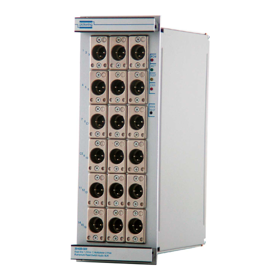
SECTION 5 - CONNECTOR INFORMATION pickering SECTION 5 - CONNECTOR INFORMATION The Module utilises XLR Audio connectors with the Front Panel Layout as below. See Section 1 and Figure 5.1. ‘Power’ LED System connected to Power Supply ‘Active’ LED Illuminates when a matrix switch is closed TEST ‘Test’... - Page 24 SECTION 5 - CONNECTOR INFORMATION pickering XLR Audio Connector 3 Way XLR Connector 1 (Top Left) 3 Way XLR Connector 2 (Top Centre) 3 Way XLR Connector 3 (Top Right) Signal Signal Signal Signal Signal Signal Signal Signal Signal 3 Way XLR Connector 4...
-
Page 25: Trouble Shooting
Refer to the Warnings and Cautions at the front of this manual INSTALLATION PROBLEMS The Plug & Play functionality of Pickering switch cards generally ensures trouble-free installation, however for the GPIB/RS-232 Interface to work correctly there must be at least one switching module present in the rack. - Page 26 SECTION 6 - TROUBLE SHOOTING pickering THIS PAGE INTENTIONALLY BLANK LOW NOISE HIGH ISOLATION MULTIPLEXER 20-620-322 Page 6.2...
-
Page 27: Maintenance Information
• Wipe the product & chassis surfaces with a clean dry anti-static cloth only. SOFTWARE UPDATE For System 10/20 modules operating in a System 10/20 chassis, no software updates are required. For the pickeringtest.com latest version of the driver please refer to our web site... - Page 28 SECTION 7 - MAINTENANCE INFORMATION pickering RELAY LOOK-UP TABLES Table 7.1 - Relay Look-up Table: 20-620-322 Signal Path (with relay energised) 20-620-322 Single 16 to 1 20-620-322 Dual 8 to 1 PCB Multiplexer Relay Bank number Multiplexer Multiplexer Path Path...
-
Page 29: Pcb And Component Layout
SECTION 7 - MAINTENANCE INFORMATION pickering PCB AND COMPONENT LAYOUT CH16 CH15 CH14 CH13 CH12 CH11 CH10 BB24 BB23 BB22 BB21 C5 C6 BB20 RL37 RL38 RL39 RL40 RL41 RL42 RL43 RL44 RL45 BB19 BB18 BB17 BB16 RL32 RL36 BB15... - Page 30 SECTION 7 - MAINTENANCE INFORMATION pickering Figure 7.2 - System 20 Universal Driver Board (A/PC/080) LOW NOISE HIGH ISOLATION MULTIPLEXER 20-620-322 Page 7.4...
Need help?
Do you have a question about the SYSTEM 10 and is the answer not in the manual?
Questions and answers