Pickering SYSTEM 10 User Manual
Gpib very high voltage multiplexer/switching modules
Hide thumbs
Also See for SYSTEM 10:
- User manual (52 pages) ,
- User manual (38 pages) ,
- User manual (36 pages)
Table of Contents
Advertisement
Quick Links
Advertisement
Table of Contents

Subscribe to Our Youtube Channel
Related Manuals for Pickering SYSTEM 10


Summary of Contents for Pickering SYSTEM 10
- Page 1 User Manual SYSTEM 10/20 GPIB Very High Voltage Multiplexer /Switching Modules (Model Nos. 20-310/320) *Please contact Pickering for alternative PXI/LXI/USB solutions Issue 4.1 July 2019 pickeringtest.com pickering VERY HIGH VOLTAGE MUX/SWITCHING MODULES 20-310/320 Page (1)
- Page 2 © COPYRIGHT (2019) PICKERING INTERFACES. ALL RIGHTS RESERVED. No part of this publication may be reproduced, transmitted, transcribed, translated or stored in any form, or by any means without the written permission of Pickering Interfaces. Technical details contained within this publication are subject to change without notice.
- Page 3 Pickering Interfaces strives to fulfil all relevant environmental laws and regulations and reduce wastes and releases to the environment. Pickering Interfaces aims to design and operate products in a way that protects the environment and the health and safety of its employees, customers and the public. Pickering Interfaces endeavours to develop and manufacture products that can be produced, distributed, used and recycled, or disposed of, in a safe and environmentally friendly manner.
-
Page 4: Product Safety
PRODUCT SAFETY SAFETY SYMBOLS The following safety symbols may be used on the product and throughout the product documentation. MEANING / DESCRIPTION SYMBOL PROTECTIVE EARTH (GROUND) To identify any terminal which is intended for connection to an external conductor for protection against electric shock in case of a fault, or the terminal of a protective earth (ground) electrode. -
Page 5: Table Of Contents
CONTENTS Copyright Statement ..............II Technical Support and Warranty ..........III Product Safety ................IV Contents (this page) ..............V Warnings and Cautions ..............VII Section 1 Technical Specification ...............1.1 Section 2 Technical Description ..............2.1 Functional Description ............2.1 Section 3 Installation ..................3.1 Pre-Operation Checks ............3.1 Hardware Installation ............3.1... - Page 6 THIS PAGE INTENTIONALLY BLANK VERY HIGH VOLTAGE MUX/SWITCHING MODULES 20-310/320 Page (VI)
-
Page 7: Warnings And Cautions
Unused slots in the System 10/20 chassis are populated with blanking plates to prevent access to user I/O signals that may be present. Blanking panels are available to order from Pickering in a variety of slot widths. If the product is not used in this manner for example by using an extender card then additional care must be taken to avoid contact with exposed signals. - Page 8 THIS PAGE INTENTIONALLY BLANK VERY HIGH VOLTAGE MUX/SWITCHING MODULES 20-310/320 Page (VIII)
-
Page 9: Technical Specification
“cold” switching (close switch before EHT load applied) high voltage applications giving reliable switching with no disruption to internal logic. *Please contact Pickering for alternative To ensure maximum high voltage isolation, all modules are PXI/LXI/USB solutions driven by a separate optically isolated driver module (Model 10-410B-004). - Page 10 EHT cabling to a minimum. If remote mounting is Very High Voltage Switch Specification not chosen then the high voltage modules may be mounted in a “Combined” System 10/20 case, however this will result in a Max Standoff Voltage: 7500V DC (7500V ACpk) increase in switching noise within the system case.
- Page 11 Ordering Information High Voltage Multiplexer/Switch Module – 20-310/320 Product Order Codes Product Customization Pickering System 20 modules are designed and manufactured 16 x Normally Open (NO) 20-310-011 on our own flexible manufacturing lines, giving complete product 8 x Changeover (NO + NC)
- Page 12 12V (HV) which operates the high voltage relay coils. Housing Local Housing of the System 10 Driver module (10-410B-004) and the System 20 High Voltage Switching Module(s) in the same chassis (yet physically separated) may be suitable for cold switching applications, however remote housing of the HV Modules in another chassis is preferred for Hot Switching applications due to the potential High Voltage switching noise generated.
-
Page 13: Technical Description
SPDT Changeover, and Dual 8x1 Channel Mux switch configurations with LEDs on the front panel indicating when the relays are energised via control signals from the relay driver board. The relay driver board is fed with data from the System 10 Driver Module 10-410B-004. Relay switching is determined by operator programming. TO FRONT... - Page 14 SECTION 2 - TECHNICAL DESCRIPTION pickering Figure 2.2 - Example System (4 x 20-310 Modules including 64 High Voltage Relays) VERY HIGH VOLTAGE MUX/SWITCHING MODULES 20-310/320 Page 2.2...
-
Page 15: Installation
The module is designed for indoor use only. PRE-OPERATION CHECKS (UNPACKING) 1. Check the module for transport damage and report any damage immediately to Pickering Interfaces. Do not attempt to install the product if any damage is evident. 2. Position the chassis relative to any other equipment the module(s) will connect with. Ensure the chassis is not connected to the electrical supply. - Page 16 10-910M (See the Pickering IEEE-488 GPIB System 10/20 Ancillaries manual for further details). (When fitted, additional modules will be automatically recognised by the interface card. See Figure 3.1). 4. If necessary fit the module guide rails as supplied with the module to both the top and bottom of the chassis in that slot position.
-
Page 17: Software Installation
SECTION 3 - INSTALLATION SECTION 3 - INSTALLATION pickering pickering Figure 3.4 - Module Insertion in a Pickering 20-935A-001 Front Access Chassis SOFTWARE INSTALLATION Refer to the Pickering manual 10-921M. pickeringtest.com For the latest version of the driver please refer to our web site where links to our Software Download page will provide the driver software for the various programming environments encountered. - Page 18 SECTION 3 - INSTALLATION pickering THIS PAGE INTENTIONALLY BLANK VERY HIGH VOLTAGE MUX/SWITCHING MODULES 20-310/320 Page 3.4...
-
Page 19: Programming Guide
Figure 4.1 - A 37 Way D-Type F/F Cable (Pickering 40-970-037-1M) (See Pickering Interfaces Connection Solutions Catalogue - available for download via the website) For programming details please refer to the 10-410B user manual and the manual for the Interface Module being used. - Page 20 SECTION 4 - PROGRAMMING GUIDE pickering THIS PAGE INTENTIONALLY BLANK VERY HIGH VOLTAGE MUX/SWITCHING MODULES 20-310/320 Page 4.2...
-
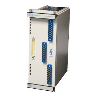
Page 21: Connector Information
SECTION 5 - CONNECTOR INFORMATION pickering SECTION 5 - CONNECTOR INFORMATION All versions have identical front panels, consisting of 3 multipole high voltage connectors and one D-type connector for module power and control, see Figure 5.1. Power LED Indicator LED's... - Page 22 SECTION 5 - CONNECTOR INFORMATION pickering 15 Way High Voltage Connector 1 Pin No. Signal Name Pin No. Signal Name Shield Interlock Interlock 15 Way High Voltage Connector 2 Pin No. Signal Name Pin No. Signal Name Shield Interlock Interlock 15 Way High Voltage Connector 3 Pin No.
- Page 23 SECTION 5 - CONNECTOR INFORMATION pickering 15 Way High Voltage Connector 1 Pin No. Signal Name Pin No. Signal Name Shield Interlock Interlock 15 Way High Voltage Connector 2 Pin No. Signal Name Pin No. Signal Name Shield Interlock Interlock 15 Way High Voltage Connector 3 Pin No.
- Page 24 SECTION 5 - CONNECTOR INFORMATION pickering 15 Way High Voltage Connector 1 Pin No. Signal Name Pin No. Signal Name C1.1 Shield C1.3 C1.2 C1.5 C1.4 C1.7 C1.5 C1.8 Interlock Interlock 15 Way High Voltage Connector 2 Pin No. Signal Name Pin No.
- Page 25 SECTION 5 - CONNECTOR INFORMATION pickering 37 Way D Type ‘X’ Connector Pin No. Signal Pin No. Signal RL10 RL12 RL11 RL14 RL13 RL16 RL15 Shield Figure 5.5 - Pin Outs for the 37 Way D-Type Control/Power Connector Notes: The 12V (LV) power supply is provided for operating the clean side Relay Control: RL of the opto-isolator circuit.
-
Page 26: 20-310/320 Interlocking
SECTION 5 - CONNECTOR INFORMATION pickering 20-310/320 Interlocking The 20-310/320 modules have the facility for an external interlock. This may be used to shutdown external high voltage sources if all connectors are not properly attached to the switching unit. Each high voltage connector has two pins dedicated to interlock (R & S), these pins are isolated from all other connections and are shorted together on the rear of the connector. -
Page 27: Trouble Shooting
High Voltage Switching Problems Your Pickering Switching module will perform reliably if operated according to the specification described in this manual. However if the module is operated outside it’s specification, specifically, if higher voltages are switched the following consequences may occur: •... - Page 28 SECTION 6 - TROUBLE SHOOTING pickering THIS PAGE INTENTIONALLY BLANK VERY HIGH VOLTAGE MUX/SWITCHING MODULES 20-310/320 Page 6.2...
-
Page 29: Maintenance Information
• Wipe the product & chassis surfaces with a clean dry anti-static cloth only. SOFTWARE UPDATE For System 10/20 modules operating in a System 10/20 chassis, no software updates are required. For the pickeringtest.com latest version of the driver please refer to our web site... - Page 30 SECTION 7 - MAINTENANCE INFORMATION pickering RELAY LOOK-UP TABLES Table 7.1 - Relay Look-up Table (All Versions) Signal Path (with relay energised) 20-310-011 20-310-211 20-320-011 Relay number (16 x SPST) (8 x SPDT) Dual 8 to 1) (Changeover) (Multiplexer) A1 to C1 A1 to C1 (NO) C1.1 to COM...
-
Page 31: Pcb And Component Layout
SECTION 7 - MAINTENANCE INFORMATION pickering PCB AND COMPONENT LAYOUT LD17 LD16 LD15 LD14 LD13 LD12 LD11 LD10 Pickering Interfaces Ltd Opto-isolated Driver Figure 7.1 - Driver Board Layout (A/PC/090) VERY HIGH VOLTAGE MUX/SWITCHING MODULES 20-310/320 Page 7.3... - Page 32 SECTION 7 - MAINTENANCE INFORMATION pickering Pickering Interfaces Ltd Shield High Voltage Relays Shield Shield Figure 7.2 - Relay Board Layout (A/PC/091) VERY HIGH VOLTAGE MUX/SWITCHING MODULES 20-310/320 Page 7.4...
-
Page 33: Appendix A Manual Control
APPENDIX A - MANUAL CONTROL pickering APPENDIX A - MANUAL CONTROL 37 Way Male D-Type Connector Pin No. Signal Pin No. Signal +12V IN RL10 RL12 RL11 RL14 RL13 RL16 RL15 ─ ─ ─ ─ ─ ─ ─ ─ ─... - Page 34 APPENDIX A - MANUAL CONTROL pickering THIS PAGE INTENTIONALLY BLANK VERY HIGH VOLTAGE MUX/SWITCHING MODULES 20-310/320 Page A.2...
-
Page 35: 20-310 Sense Line Connections
APPENDIX B - 20-310 SENSE LINE CONNECTIONS pickering APPENDIX B - 20-310 SENSE LINE CONNECTIONS 20-310 sense line connections D.C.H 10/04/13 Sense line pull-up resistors (10K in 10-410B-004) External supply for sense line pull-up resistors (5V DC in 10- 410B-004) - Page 36 APPENDIX B - 20-310 SENSE LINE CONNECTIONS pickering THIS PAGE INTENTIONALLY BLANK VERY HIGH VOLTAGE MUX/SWITCHING MODULES 20-310/320 Page B.2...
Need help?
Do you have a question about the SYSTEM 10 and is the answer not in the manual?
Questions and answers