Table of Contents
Troubleshooting

Related Manuals for Kärcher WINDSOR Chariot 2 iVac 24 ATV


Summary of Contents for Kärcher WINDSOR Chariot 2 iVac 24 ATV
- Page 1 Chariot 2 iVac 24 ATV Vacuum Operating Instructions (ENG) MODELS: CV24 1.012-576.0 CVC24 1.012-577.0 From Serial Number (Ref No. 2*) * See Serial Number page in Spare Parts List or call manufacturer. 86398780-C 04/16/16...
-
Page 2: Machine Data Label / Overview
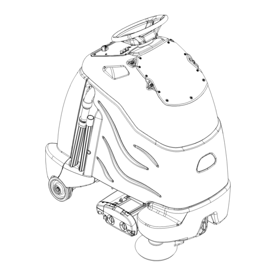
Machine Data Label / Overview OVERVIEW The Chariot® iVacuum 24™ is a battery powered, stand-on, wide area vacuum intended for commercial use. The Chariot® iVacuum 24™ brushes and vacuums debris from indoor hard and carpeted surfaces and deposits the debris in the debris tray and filter bags. The unit also has an accessory wand and hose for cleaning small areas and non-floor surfaces. -
Page 3: Table Of Contents
Table of Contents Machine Data Label / Overview ....2 Table of Contents......3 How To Use This Manual. -
Page 4: How To Use This Manual
How To Use This Manual This manual contains the following sections: The SAFETY section contains important information regarding hazardous or unsafe practices of the • How to Use This Manual machine. Levels of hazards are identified that could • Safety result in product damage, personal injury, or severe •... -
Page 5: Safety
Safety IMPORTANT SAFETY INSTRUCTIONS When using this machine, basic precaution must always be followed, including the following: READ ALL INSTRUCTIONS BEFORE USING THIS MACHINE. To reduce the risk of fire, electric shock, or injury: Use only indoors. Do not use outdoors or expose to rain. This appliance is for dry use only. Use only as described in this manual. - Page 6 Safety MESURES DE SÉCURITÉ IMPORTANTES Lors de l'utilisation d'un appareil à batteries, il est nécessaire de respecter systématiquement des mesures de sécurité de base, comme suit : NOTE DE TOUTES CES MESURES AVANT D'UTILISER CETTE MACHINE. Pour réduire les risques d'incendie, de chocs électriques, ou de blessures : N'utiliser cette machine qu'en intérieur.
-
Page 7: Hazard Intensity Level
Safety The following symbols are used throughout this guide as indicated in their descriptions: HAZARD INTENSITY LEVEL There are three levels of hazard intensity identified by signal words -WARNING and CAUTION and FOR SAFETY. The level of hazard intensity is determined by the following definitions: WARNING - Hazards or unsafe practices which COULD result in severe personal injury or death. - Page 8 Safety Les symboles ci-dessous sont utilisés à travers ce manuel comme illustré dans leurs descriptions : DEGRÉS DE RISQUES EN CAS DE DANGER Il existe trois degrés de risques identifiés par les termes signalétiques -AVERTISSEMENT et ATTENTION et POUR VOTRE SÉCURITÉ. Le degré de risque est défini de la manière suivante: AVERTISSEMENT - Dangers ou méthodes dangereuses qui POURRAIENT provoquer de graves blessures ou entraîner la mort.
-
Page 9: Safety Label Locations
Safety Safety Label Locations These drawings indicate the location of safety labels on the machine. If at any time the labels become illegible, promptly replace them. EMPLACEMENT DE L'ÉTIQUETTE DE SÉCURITÉ REMARQUE : Ces dessins indiquent l'emplacement des étiquettes de sécurité sur la machine. Si, à tout moment, les étiquettes deviennent illisibles, contactez votre représentant autorisé... -
Page 10: Operations
Operations Technical Specifications ITEM DIMENSION/CAPACITY Nominal power 1224 W Rated Voltage 36 Volts DC Rated Amperage 34 amps Batteries 3 X12 Volt 130 AH @ 20 hr. rate Battery Compartment Dimensions 20-1/2 in. x 13 in. x 10 in. tall (330mm x 521mm x 254mm) Propelling Motor .38 HP (280 W) Cylindrical Brush Motor... - Page 11 Operations ITEM MEASURE Height 51.8 in (1316 mm) Length 44.0 in (1118 mm) Width without deck 24.5 in (622 mm) Width of deck 23.25 in (581 mm) Width with side broom 25.9 in (658 mm) WIDTH LENGTH HEIGHT This appliance is not intended for use by persons (including children) with reduced physical, sensory or mental capabilities, or lack of experience and knowledge, unless they have been given supervision or instruction concerning use of the appliance by a person responsible for their safety.
-
Page 12: How This Machine Works
Operations The function of the operator control system is to control How This Machine Works the direction and speed of the machine. The directional The Chariot® iVacuum 24 ATV™ is a battery powered, control system consists of the direction control switch, self-propelled, vacuum intended for commercial use. -
Page 13: Components
Operations Components 1. Accessory Hose 2. Brush Deck 3. Console 4. Control Panel 5. Main Cover 6. Pedal Platform 7. Rear Cover 8. Side Broom 9. Vacuum Bag 86398780 Operator Manual iVac 24 ATV... -
Page 14: Drive Controls
Operations Drive Controls 86398780 Operator Manual iVac 24 ATV... - Page 15 Operations 1. Key Switch 2. Emergency Stop/Brake Switch 3. Directional Control / Drive Reset Switch 4. Throttle Pedal 5. Horn Button 6. Steering Wheel 7. Speed Control 8. Battery Discharge Indicator Light 9. Hour Meter 10. Operator Presence Switch 1. KEY SWITCH Controls the power for machine functions.
- Page 16 Operations 4. THROTTLE PEDAL Controls the speed of the vehicle within the speed control setting selected. Pressing the pedal causes the machine to travel in the direction selected by the Directional Control Switch. To increase speed, increase pressure on the pedal. To decrease speed, decrease pressure on the pedal.
- Page 17 Operations 8. BATTERY DISCHARGE INDICATOR Indicates the charge level of the batteries. The indicator will be illuminated if the batteries have a sufficient charge. A slow, continous flash indicates the batteries require charging. The Battery Lockout function will activate when the batteries are low. Once active, the LED status indicator will begin to flash slowly and the controller will inhibit the side broom, main brushes, and vacuum operation.
-
Page 18: Vacuum Controls
Operations Vacuum Controls 1. Function Mode Switch The first two positions are for transport only. See drive controls section. Light vacuuming This mode is used for light vacuuming. In this mode the machine will propel at fast speed. The ‘floating’ brush deck is in the down position. The brushes will agitate, the side broom will bring debris into the path of the deck. -
Page 19: Pre-Run Machine Inspection
Operations Pre-run Machine Inspection Emergency Stop Procedures Do a pre-run inspection to find possible problems that 1. Release the throttle pedal by lifting right foot. could cause poor performance or lost time from break- 2. Turn machine power off with key switch by turning down. -
Page 20: Normal Vacuuming
Operations Normal Vacuuming To Begin Vacuuming Plan the vacuuming pattern in advance. The longest track is around the perimeter of the area to be cleaned. For efficient operation, the runs should be the longest When operating the machine around people, pay possible without turning or stopping. -
Page 21: To Stop Vacuuming
Operations 7. Tilt back panel to retrieve a new clean paper bag To Stop Vacuuming from the storage compartment in left side wall of 1. Remove foot from throttle pedal allowing pedal to main cover. return to neutral. 8. Return back panel to operating position. 2. -
Page 22: Maintenance
Maintenance Service Schedule BEFORE AFTER EACH EACH MAINTENANCE WORK 50 HRS WORK PERIOD PERIOD Check water level of batteries after charging; add distilled water if necessary Check that the vacuum box lid seal tightly Visually check for damaged or worn tires. Check vacuum hose connections. -
Page 23: Batteries
Maintenance Batteries 1. Cover Retainer Latch 2. Rear Cover 3. Battery Connector-Machine 4. Batteries 5. Battery Tray 86398780 Operator Manual iVac 24 ATV... - Page 24 Maintenance Batteries (Wet Cell) The batteries provide the power to operate the machine. The batteries require regular maintenance to keep them operating at peak efficiency. The machine batteries will hold their charge for long periods of time, but they can only be charged a certain number of times.
- Page 25 Maintenance Battery Maintenance 1. When cleaning the batteries, use a solution of baking soda and water. Do not allow the cleaning When servicing machine, avoid contact with fluid to enter the battery cells, electrolyte will be battery acid. neutralized. 2. Maintain the proper electrolyte level in each battery cell.
- Page 26 Maintenance Checking Battery Specific Gravity Use a hydrometer to check the battery specific gravity. CHECKING GRAVITY a. Hydrometer Battery b. Battery NOTE: Do not take readings immediately after adding distilled water, if the water and acid are not thoroughly mixed, the reading may not be accurate. Check the hydrometer readings against this chart.
- Page 27 Maintenance Use a 36 volt, 20 amp maximum output DC charger Charging Batteries which will automatically shut off when the batteries are fully charged. 1. Stop the machine in a clean, well ventilated area When servicing machine, avoid contact with next to the charger.
- Page 28 Maintenance 5. Replace the battery caps, and leave them in place 7. Disconnect main positive lead and secure cable while charging. terminals away from batteries. 6. Unplug the battery connector from the machine. 8. Loosen both terminals on each jumper cable and remove one at a time.
-
Page 29: Delta Q Ic650 Charger Maintenance Instructions
Maintenance Delta Q IC650 Charger Maintenance Instructions 1. Do not expose charger to oil, dirt, mud or direct heavy water spray when cleaning the vehicle or machine. 2. The enclosure of the charger meets IP66, making it dust-tight and protected against powerful water jets. The AC inlet connection itself, when mated, is rated to IP20, which is not protected against water. -
Page 30: Delta Q Ic650 Charger Operating Instructions
Maintenance Delta Q IC650 Charger Operating Instructions - The charger may become hot during charging. Use hand protection to safely handle the charger during charging. - Extension cords must be a 3-wire cord no longer than 30m (100') at 10 AWG or 7.5m (25') at 16 AWG, per UL guidelines. -
Page 31: Selecting A Charge Profile
Maintenance *Process will time out and profile will remain Selecting a Charge Profile unchanged if there is 15 seconds of inactivity, a profile 1. Disconnect AC input from the charger, or from the number is allowed to display three times, or if AC power wall outlet. -
Page 32: Configuring The Ic650 Charger Using A Usb Flash Drive
Maintenance Configuring the IC650 Charger Using a USB Flash Drive Using the Delta Q software, USB storage drives can be pre-programmed to certain charger configuration. To use the USB port, follow these steps: 1. Insert the USB flash drive at any time, except during a charge cycle. Stop the charge cycle by removing AC power or the DC connection to the batteries. -
Page 33: Charge Tracking Data
Maintenance Charge Tracking Data All IC650 Chargers record data such as amp hours returned, charge cycle completion or interruption, and the charge profile being used. This data can be very useful in vehicle or machine diagnostics. To retrieve this data, follow these steps: 1. -
Page 34: Circuit Protection
Maintenance Circuit Protection Circuit Breakers 3 A Fuse Circuit breakers interrupt the flow of power in the event of an electrical overload. When a circuit breaker is tripped, reset it by pressing the exposed button. If a circuit breaker continues to trip, the cause of the electrical overload should be found and corrected. -
Page 35: Vacuum Diverter Valve Maintenance
Maintenance Vacuum Diverter Valve Maintenance For maintenance and removal of the vacuum diverter valve follow the steps below. 4. Remove the three (3) screws and washers 1. Remove hoses from diverter valve. retaining the diverter valve assembly to the console. 2. - Page 36 Maintenance Brush Deck 1. Debris Tray 2. Brush Deck Door 3. Side Broom 4. Deck Lift Actuator 86398780 Operator Manual iVac 24 ATV...
-
Page 37: Brush Removal
Maintenance Brush Deck Debris Tray Removal The dual cylindrical head is designed to agitate the 1. Release the debris tray spring clip. carpet while vacuuming. The first brush pushes debris 2. Slide the debris tray away from machine. backwards. The second brush, brushing forward picks up debris and throws it into the debris tray. -
Page 38: Remove Brush Deck
Maintenance Brush Motor Carbon Brush Replacement 1. Scribe alignment mark on motor barrel to motor cap. Remove two bolts. Do not use a pressure washer to clean around the brush motors. Use tap pressure only. 2. Remove end cap from motor. NOTE: Motors contain two wave washers in cap. - Page 39 Maintenance 8. Remove move three (3) screws that secure To Repair or Replace Vacuum Motor vacuum motor. Replace motor. 1. Remove four (4) screws from top of control panel. 2. Tip control panel back from console to expose vacuum motor wires. 3.
-
Page 40: Drive Motor-From Serial Number (3*)
Maintenance Drive Motor-From Serial Number (3*) Drive Chain Tension The drive chain should deflect about 1/4 inch on either Drive Motor Carbon Brush Replacement side of the loop when the opposite side is tight. To adjust chain tension: 1. Remove bumper. Do not use a pressure washer to clean around the brush motors. - Page 41 Maintenance Brake Override 5. Push the machine slowly. Take care as voltage is generated while pushing the machine and may 1. Disconnect battery to prevent injury. cause the controller to temporarily stop the machine. 2. Turn wheel slightly to the right. 3.
-
Page 42: Drive Motor-Prior To Serial Number (3*)
Maintenance Drive Motor-Prior to Serial Number (3*) Drive Chain Tension The drive chain should deflect about 1/4 inch on either Drive Motor Carbon Brush Replacement side of the loop when the opposite side is tight. To adjust chain tension: 1. Remove bumper. Do not use a pressure washer to clean around the brush motors. - Page 43 Maintenance Lever access Drive gear disengaged Turn wheel to left and reach up under bumper and steel Machine can be pushed or towed (slowly). brake. When disengaged the machine rolls easily. Disengage on a level surface. Rotate lever firmly in direction of arrow. Drive gear engaged Machine can be driven.
-
Page 44: Machine Tie-Downs
Maintenance Preparation for Loading/Unloading Trailer Before loading or unloading machine from trailer, brush deck must be in the up position. When transporting the machine on a trailer or in a truck, in addition to using tie-downs, be sure to block the tires to prevent the machine from rolling. -
Page 45: Troubleshooting
Maintenance Troubleshooting PROBLEM CAUSE SOLUTION No machine function Console lid is open Close console lid No power to machine Battery disconnected Check all battery cable connections Emergency shut-off activated Reset Battery cables corroded Clean connections Faulty key switch Replace switch Batteries not plugged in Plug batteries in On Board charger plugged in... - Page 46 Maintenance Troubleshooting PROBLEM CAUSE SOLUTION Vacuum motor does not run, or Faulty vacuum circuit or switch Check wires & connections runs slowly Worn vacuum motor brushes Replace brushes, check commutator Vacuum circuit breaker tripped Reset circuit breaker Vacuum and brush do not turn on Circuit breaker tripped Reset Full bag or clog in system (bag full light Replace bag, empty debris tray, check...
-
Page 47: Battery Discharge Indicator Troubleshooting
Maintenance Battery Discharge Indicator Troubleshooting The battery indicator flashes when a problem occurs. The table below list solutions for the indicated problems. Number of Problem Solution flashes The battery needs charging, there is a bad connection to If the connections are good, try the battery or dependent on the programming, may charging the battery. -
Page 48: Suggested Spare Parts
Suggested Spare Parts 86398780 Operator Manual iVac 24 ATV... - Page 49 Notes 86398780 Operator Manual iVac 24 ATV...
Need help?
Do you have a question about the WINDSOR Chariot 2 iVac 24 ATV and is the answer not in the manual?
Questions and answers