KROHNE OPTISOUND 3010 C Handbook
Ultrasonic level transmitter
Hide thumbs
Also See for OPTISOUND 3010 C:
- Handbook (52 pages) ,
- Quick setup manual (16 pages) ,
- Manual (16 pages)
Table of Contents
Advertisement
Quick Links
Advertisement
Table of Contents

Related Manuals for KROHNE OPTISOUND 3010 C


Summary of Contents for KROHNE OPTISOUND 3010 C
- Page 1 OPTISOUND 3010 C Handbook Ultrasonic Level Transmitter Foundation Fieldbus...
-
Page 2: Table Of Contents
Maintenance ........................39 7.2 Rectify faults ........................39 Exchanging the electronics module ................39 Instrument repair ......................40 Dismount Dismounting steps......................41 Disposal ......................... 41 Supplement Technical data ........................ 42 Foundation Fieldbus ....................... 45 Dimensions ........................49 OPTISOUND 3010 C • Foundation Fieldbus... - Page 3 Contents Safety instructions for Ex areas Take note of the Ex specific safety instructions for Ex applications. These instructions are attached as documents to each instrument with Ex approval and are part of the operating instructions manual. Editing status: 2015-08-18 OPTISOUND 3010 C • Foundation Fieldbus...
-
Page 4: About This Document
This arrow indicates a single action. Sequence of actions Numbers set in front indicate successive steps in a procedure. Battery disposal This symbol indicates special information about the disposal of bat- teries and accumulators. OPTISOUND 3010 C • Foundation Fieldbus... -
Page 5: For Your Safety
During work on and with the device the required personal protective equipment must always be worn. Appropriate use OPTISOUND 3010 C is a sensor for continuous level measurement. You can find detailed information about the area of application in chapter "Product description". Operational reliability is ensured only if the instrument is properly used according to the specifications in the operating instructions manual as well as possible supplementary instructions. -
Page 6: Safety Label On The Instrument
The safety approval markings and safety tips on the device must be observed. CE conformity The device fulfills the legal requirements of the applicable EC guide- lines. By affixing the CE marking, we confirm successful testing of the product. 2.7 Fulfillment of NAMUR recommendations NAMUR is the automation technology user association in the process industry in Germany. The published NAMUR recommendations are accepted as the standard in field instrumentation. The device fulfills the requirements of the following NAMUR recom- mendations: • NE 21 – Electromagnetic compatibility of equipment • NE 53 – Compatibility of field devices and display/adjustment components For further information see www.namur.de. OPTISOUND 3010 C • Foundation Fieldbus... -
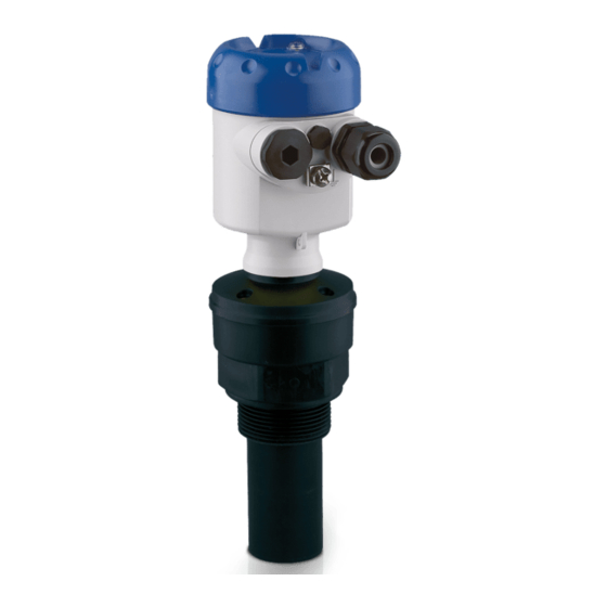
Page 7: Product Description
Housing with electronics • Housing cover with integrated display and adjustment module (optional) The components are available in different versions. Fig. 1: OPTISOUND 3010 C - version with plastic housing Housing cover with integrated display and adjustment module (optional) Housing with electronics 3 Process fitting with transducer Type label... -
Page 8: Principle Of Operation
Technical data: For example approvals, process temperature, process fitting/material, signal output, power supply, protection Principle of operation Application area OPTISOUND 3010 C is an ultrasonic sensor for continuous level measurement. It is suitable for liquids and solids in virtually all indus- tries, particularly in the water and waste water industry. Functional principle The transducer of the ultrasonic sensor transmits short ultrasonic pulses to the measured product. These pulses are reflected by... - Page 9 Not exposed to corrosive media • Protected against solar radiation • Avoiding mechanical shock and vibration • Storage and transport Storage and transport temperature see chapter "Supplement - temperature Technical data - Ambient conditions" • Relative humidity 20 … 85 % OPTISOUND 3010 C • Foundation Fieldbus...
-
Page 10: Mounting
You can also install the display and adjustment module in four different positions (each displaced by 90°). Moisture Use the recommended cables (see chapter "Connecting to power supply") and tighten the cable gland. You can give your OPTISOUND 3010 C additional protection against moisture penetration by leading the connection cable downward in front of the cable entry. Rain and condensation water can thus drain off. This applies mainly to outdoor mounting as well as installation in areas where high humidity is expected (e.g. through cleaning pro- cesses) or on cooled or heated vessels. -
Page 11: Mounting Instructions
C. Low pressure or vacuum does, however, damp the ultrasonic pulses. This influences the measuring result, particularly if the level is very low. With pressures under -0.2 bar (-20 kPa) you should use a different measuring principle, e.g. radar or guided radar (TDR). Mounting instructions Screwing in Screw OPTISOUND 3010 C into the mounting socket with an ap- propriate spanner applied to the hexagon of the process fitting. Max. torque see chapter "Technical data". OPTISOUND 3010 C • Foundation Fieldbus... - Page 12 The housing must not be used to screw the instrument in! Applying tightening force can damage internal parts of the housing. Installation position When mounting the OPTISOUND 3010 C, keep a distance of at least 200 mm (7.874 in) to the vessel wall. If the sensor is installed in the center of dished or round vessel tops, multiple echoes can arise.
- Page 13 Fig. 7: Recommended socket mounting If the reflective properties of the medium are good, you can mount OPTISOUND 3010 C on sockets which are higher than the length of the transducer. You will find recommended values for socket heights in the following illustration. The socket end should be smooth and burr- free, if possible also rounded. Carry out a false echo storage.
- Page 14 "clear view" to the measured product. In case of existing vessel installations, a false echo storage should be carried out during setup. OPTISOUND 3010 C • Foundation Fieldbus...
- Page 15 Agitators If there are agitators in the vessel, a false signal storage should be carried out with the agitators in motion. This ensures that the interfer- ing reflections from the agitators are saved with the blades in different positions. Fig. 12: Agitators Do not mount the instruments in or above the filling stream. Make sure Inflowing medium that you detect the product surface, not the inflowing product. OPTISOUND 3010 C • Foundation Fieldbus...
- Page 16 Standpipe measurement By using a standpipe (surge or bypass tube), the influence of vessel installations, foam generation and turbulence is excluded. Standpipes must extend all the way down to the requested min. level, as measurement is only possible within the tube. OPTISOUND 3010 C • Foundation Fieldbus...
- Page 17 Fig. 14: Standpipe in the tank Vent hole ø 5 … 10 mm OPTISOUND 3010 C can be used from tube diameters of 40 mm. Avoid large gaps and thick welding joints when connecting the tubes. Generally carry out a false echo storage.
- Page 18 90° Fig. 16: Flow measurement with Khafagi-Venturi flume: d = Min. distance to sen- sor; h = max. filling of the flume; B = tightest constriction in the flume max. Position sensor 2 Venturi flume In general, the following points must be observed: • Installation of the sensor at the inlet side • Installation in the centre of the flume and vertical to the liquid surface • Distance to the Venturi flume • Min. distance of the sensor to max. storage level OPTISOUND 3010 C • Foundation Fieldbus...
-
Page 19: Connecting To Power Supply
The cable screens to the power supply unit and to the next distributor must be connected to each other and also connected to ground potential via a ceramic capacitor (e.g. 1 nF, 1500 V). The low frequency potential equalisation currents are thus suppressed, but the protective effect against high frequency interference signals remains. OPTISOUND 3010 C • Foundation Fieldbus... -
Page 20: Connection Procedure
10. Connect the screen to the internal ground terminal, connect the outer ground terminal to potential equalisation 11. Tighten the compression nut of the cable entry gland. The seal ring must completely encircle the cable 12. Screw the housing lid back on The electrical connection is finished. OPTISOUND 3010 C • Foundation Fieldbus... -
Page 21: Wiring Plan, Single Chamber Housing
Fig. 17: Connection steps 6 and 7 Wiring plan, single chamber housing The following illustrations apply to the non-Ex as well as to the Ex-ia version. Housing overview Fig. 18: Material versions, single chamber housing Plastic Aluminium Stainless steel Filter element for air pressure compensation OPTISOUND 3010 C • Foundation Fieldbus... -
Page 22: Wiring Plan, Double Chamber Housing
Ground terminal for connection of the cable screen Wiring plan Display I 2 C Fig. 20: Wiring plan, single chamber housing 1 Voltage supply, signal output Wiring plan, double chamber housing The following illustrations apply to the non-Ex as well as to the Ex-ia version. OPTISOUND 3010 C • Foundation Fieldbus... - Page 23 5 6 7 8 Fig. 22: Electronics compartment, double chamber housing Simulation switch ("on" = simulation mode) Spring contacts for display and adjustment module Interface for service Internal connection cable to the connection compartment Ground terminal for connection of the cable screen OPTISOUND 3010 C • Foundation Fieldbus...
-
Page 24: Switch-On Phase
I 2 C Fig. 24: Wiring plan, double chamber housing 1 Voltage supply, signal output Switch-on phase Switch-on phase After connecting OPTISOUND 3010 C to power supply or after a voltage recurrence, the instrument carries out a self-check for approx. 30 seconds: • Internal check of the electronics •... -
Page 25: Set Up With The Display And Adjustment Module
The display and adjustment module is powered by the sensor, an ad- ditional connection is not necessary. Fig. 25: Insert display and adjustment module Note: If you intend to retrofit the instrument with a display and adjustment module for continuous measured value indication, a higher lid with an inspection glass is required. OPTISOUND 3010 C • Foundation Fieldbus... -
Page 26: Adjustment System
By pushing the [OK] and [ESC] keys simultaneously for more than 5 s, a return to the basic menu is caused. The menu language is then switched over to "English". OPTISOUND 3010 C • Foundation Fieldbus... -
Page 27: Setup Steps
Basic adjustment - Min. adjustment 1. Move from the measured value display to the main menu by pushing [OK]. ▶ Basic adjustment Display Diagnostics Service Info 2. Select the menu item "Basic adjustment" with [->] and confirm with [OK]. Now the menu item "Min. adjustment" is displayed. OPTISOUND 3010 C • Foundation Fieldbus... - Page 28 Through this additional selection, the sensor is adapted perfectly to the product and measurement reliability, particularly in products with poor reflective properties, is considerably increased. Enter the requested parameters via the appropriate keys, save your settings and jump to the next menu item with the [->] key. OPTISOUND 3010 C • Foundation Fieldbus...
- Page 29 In this menu item you can enter an unambiguous designation for the sor TAG sensor, e.g. the measurement loop name or the tank or product des- ignation. In digital systems and in the documentation of larger plants, a singular designation should be entered for exact identification of individual measuring points. OPTISOUND 3010 C • Foundation Fieldbus...
- Page 30 The measurement reliability equals signal strength minus noise. The higher the value, the more reliable the measurement. With a function- ing measurement, the values are > 10 dB. OPTISOUND 3010 C • Foundation Fieldbus...
- Page 31 The following functions are available with "Echo and false echo curve": • "X-Zoom": Zoom function for the meas. distance • "Y-Zoom": 1, 2, 5 and 10x signal magnification in "dB" • "Unzoom": Reset the presentation to the nominal measuring range without magnification In the menu item "Trend curve" the following are available: • "X-Zoom": Resolution – 1 minute – 1 hour OPTISOUND 3010 C • Foundation Fieldbus...
- Page 32 Service - Extended set- The menu item "Extended setting" offers the possibility to optimise ting OPTISOUND 3010 C for applications in which the level changes very quickly. To do this, select the function "Quick level change > 1 m/min.". Extended setting quick level change > 1 m/min.
- Page 33 If the "Reset" is carried out, the sensor resets the values of the follow- ing menu items to the reset values (see chart): Function Reset value Max. adjustment 0 m(d) Min. adjustment Meas. range end in m(d) Medium Liquid Vessel form not known Damping Linearization Linear Sensor-specific basic adjustment. Depending on the sensor type, see chapter "Technical data". OPTISOUND 3010 C • Foundation Fieldbus...
- Page 34 A description of the function is available in the operating instructions manual "Display and adjustment module". The following data are read out or written with this function: Special parameters are parameters which are set customer-specifically on the service level with the adjustment software PACTware. OPTISOUND 3010 C • Foundation Fieldbus...
- Page 35 In this menu item the most important sensor information can be displayed: • Instrument type • Serial number: 8-digit number, e.g. 12345678 Instrument type Serial number 12345678 • Date of manufacture: Date of the factory calibration, e.g. 24. March 2015 • Software version: Edition of the sensor software, e.g. 3.80 OPTISOUND 3010 C • Foundation Fieldbus...
-
Page 36: Menu Schematic
Basic adjustment ▶ Basic adjustment Display Diagnostics Service Info Min. adjustment Max. adjustment Medium Vessel form 000.0 % 100.0 % Liquid Storage tank 10.000 m(d) 0.000 m(d) 1.245 m(d) 6.789 m(d) Damping Linearisation curve Linear OPTISOUND 3010 C • Foundation Fieldbus... - Page 37 ▶ Service Info False signal suppression Extended setting Simulation Reset Change now? Fast Start simulation? Reset now? level change (> 1 m/min.) Unit of measurement Language Copy sensor data m(d) German Copy sensor data? Enable? OPTISOUND 3010 C • Foundation Fieldbus...
-
Page 38: Saving The Parameter Adjustment Data
They are thus available for multiple use or service purposes. If OPTISOUND 3010 C is equipped with a display and adjustment module, the most important data can be read out of the sensor into the display and adjustment module. -
Page 39: Maintenance And Fault Rectification
If the electronics module is defective, it can be replaced by the user. In Ex applications, only instruments and electronics modules with ap- propriate Ex approval may be used. If there is no electronics module available on site, one can be ordered from the Krohne agency serving you. OPTISOUND 3010 C • Foundation Fieldbus... -
Page 40: Instrument Repair
By doing this you help us carry out the repair quickly and without hav- ing to call back for needed information. • Print and fill out one form per instrument • Clean the instrument and pack it damage-proof • Attach the completed form and possibly also a safety data sheet to the instrument OPTISOUND 3010 C • Foundation Fieldbus... -
Page 41: Dismount
WEEE directive. Correct disposal avoids negative effects on humans and the environ- ment and ensures recycling of useful raw materials. Materials: see chapter "Technical data" If you have no way to dispose of the old instrument properly, please contact us concerning return and disposal. OPTISOUND 3010 C • Foundation Fieldbus... -
Page 42: Supplement
Transmission rate 31.25 Kbit/s Current value 10 mA, ±0.5 mA Resolution, digital > 1 mm (0.039 in) Input variable Measured variable distance between lower edge of the transducer and product surface Measuring range Ʋ Liquids up to 5 m (16.4 ft) Ʋ Bulk solids up to 2 m (6.562 ft) Dead zone 0.25 m (0.82 ft) OPTISOUND 3010 C • Foundation Fieldbus... - Page 43 > 3 s (dependent on the parameter adjustment) Measuring accuracy Resolution, general max. 1 mm Deviation see diagram 10 mm 4 mm -4 mm -10 mm Fig. 28: Deviation OPTISOUND 3010 C Influence of the ambient temperature to the sensor electronics Average temperature coefficient of the 0.06 %/10 K zero signal (temperature error) Ambient conditions Ambient, storage and transport tempera- -40 … +80 °C (-40 … +176 °F) ture Process conditions Process pressure -20 … 200 kPa/-0.2 … 2 bar (-2.9 … 29 psig)
- Page 44 Operating voltage with illuminated display and adjustment module Ʋ Non-Ex instrument 12 … 32 V DC Ʋ Ex ia instrument 12 … 24 V DC Ʋ Ex-d instrument 20 … 32 V DC Power supply by/max. number of sensors Ʋ Fieldbus max. 32 (max. 10 with Ex) Tested according to the guidelines of German Lloyd, GL directive 2. OPTISOUND 3010 C • Foundation Fieldbus...
-
Page 45: Foundation Fieldbus
C! a nnel ! ! ! Secondary Value 2 AI ! C! a nnel ! ! ! Tem! e rature Fig. 29: OPTISOUND 3010 C measured value processing A suitable cable is required for maintaining the protection rating. OPTISOUND 3010 C • Foundation Fieldbus... - Page 46 Sensor reference plane cal_level_hi [%] Calibration Highest Point cal_level_lo [%] Calibration Lowest Point Fig. 30: Adjustment OPTISOUND 3010 C Parameter list for Device revision 3.0 The following list contains the most important parameters and their meaning: • primary_value – This is the process value after adjustment and Linearization with the status of the transducer block •...
- Page 47 • begin_of_operation_range – Set up to suit the process conditions • product_type – Set up to suit the process conditions. If Special-Parameter adjustment has been utilized this parameter cannot be written • liquids_medium_type – Set up to suit the process conditions. If Special-Parameter adjustment has been utilized this parameter cannot be written • solids_medium_type – Set up to suit the process conditions. If Special-Parameter adjustment has been utilized this parameter cannot be written OPTISOUND 3010 C • Foundation Fieldbus...
- Page 48 – Holds the maximum process temperature. Write access resets to current value. Unit derives from 'Temperature.unit' • min_peak_temperature_value – Holds the minimum process temperature. Write access resets to current value. Unit derives from 'Temperature.unit' OPTISOUND 3010 C • Foundation Fieldbus...
-
Page 49: Dimensions
Plastic housing Stainless steel housing Aluminium double chamber housing Aluminium housing OPTISOUND 3010 C 60mm ") G1½A / 1½"NPT ø 39mm ") ø 74mm ") Fig. 32: OPTISOUND 3010 C Dead zone: 0.25 m (0.82 ft) Measuring range: with liquids up to 5 m (16.4 ft), with solids up to 2 m (6.562 ft) OPTISOUND 3010 C • Foundation Fieldbus... - Page 50 9 Supplement Trademark All the brands as well as trade and company names used are property of their lawful proprietor/ originator. OPTISOUND 3010 C • Foundation Fieldbus...
- Page 51 Notes OPTISOUND 3010 C • Foundation Fieldbus...
- Page 52 Products and systems for the oil and gas industry KROHNE Messtechnick GmbH & Co. KG Ludwig-Krohne-Straße 5 D-47058 Duisburg Tel.: +49 (0) 203 301 0 Tel.: +49 (0) 203 301 10389 info@krohne.de The current list of all KROHNE contacts and addresses can be found at: www.krohne.com...
Need help?
Do you have a question about the OPTISOUND 3010 C and is the answer not in the manual?
Questions and answers