KROHNE OPTISOUND 3020 C Handbook
Ultrasonic level transmitter
Hide thumbs
Also See for OPTISOUND 3020 C:
Table of Contents
Advertisement
Quick Links
Advertisement
Table of Contents

Related Manuals for KROHNE OPTISOUND 3020 C


Summary of Contents for KROHNE OPTISOUND 3020 C
- Page 1 OPTISOUND 3020 C Handbook Ultrasonic Level Transmitter Four-wire 4 … 20 mA/HART...
-
Page 2: Table Of Contents
How to proceed if a repair is necessary ................41 Dismount..........................42 Dismounting steps......................42 Disposal ......................... 42 Supplement ..........................43 Technical data ........................ 43 Dimensions ........................46 Trademark ........................48 OPTISOUND 3020 C • Four-wire 4 … 20 mA/HART... - Page 3 Contents Safety instructions for Ex areas: Take note of the Ex specific safety instructions for Ex applications. These instructions are attached as documents to each instrument with Ex approval and are part of the operating instructions. Editing status: 2022-03-07 OPTISOUND 3020 C • Four-wire 4 … 20 mA/HART...
-
Page 4: About This Document
The dot set in front indicates a list with no implied sequence. Sequence of actions Numbers set in front indicate successive steps in a procedure. Disposal This symbol indicates special instructions for disposal. OPTISOUND 3020 C • Four-wire 4 … 20 mA/HART... -
Page 5: For Your Safety
During work on and with the device, the required personal protective equipment must always be worn. Appropriate use OPTISOUND 3020 C is a sensor for continuous level measurement. You can find detailed information about the area of application in chapter " Product description". Operational reliability is ensured only if the instrument is properly used according to the specifications in the operating instructions manual as well as possible supplementary instructions. -
Page 6: 2.6 Fulfillment Of Namur Recommendations
Installations in the US shall comply with the relevant requirements of the National Electrical Code (ANSI/NFPA 70). Installations in Canada shall comply with the relevant requirements of the Canadian Electrical Code. OPTISOUND 3020 C • Four-wire 4 … 20 mA/HART... -
Page 7: Product Description
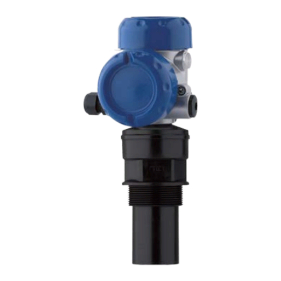
Housing with electronics • Housing cover, optionally available with display and adjustment module The components are available in different versions. Fig. 1: OPTISOUND 3020 C, version with plastic housing Housing lid with integrated display and adjustment module (optional) Housing with electronics 3 Process fitting with transducer Type label The type label contains the most important data for identification and use of the instrument: •... -
Page 8: Principle Of Operation
Technical data: For example approvals, process temperature, process fitting/material, signal output, voltage supply, protection Principle of operation Application area OPTISOUND 3020 C is an ultrasonic sensor for continuous level measurement. It is suitable for liquids and solids in virtually all indus- tries, particularly in the water and waste water industry. Functional principle The transducer of the ultrasonic sensor transmits short ultrasonic pulses to the measured product. These pulses are reflected by... - Page 9 • Relative humidity 20 … 85 % Lifting and carrying With instrument weights of more than 18 kg (39.68 lbs) suitable and approved equipment must be used for lifting and carrying. OPTISOUND 3020 C • Four-wire 4 … 20 mA/HART...
-
Page 10: Mounting
Prior to setup you have to replace these protective caps with ap- proved cable glands or close the openings with suitable blind plugs. The reference plane for the measuring range is the lower edge of the Reference plane for measuring range transducer. OPTISOUND 3020 C • Four-wire 4 … 20 mA/HART... - Page 11 (max. measuring distance) Measuring range Pressure/Vacuum Gauge pressure in the vessel does not influence OPTISOUND 3020 C. Low pressure or vacuum does, however, damp the ultrasonic pulses. This influences the measuring result, particularly if the level is very low. With pressures under -0.2 bar (-20 kPa) you should use a different measuring principle, e.g. radar or guided radar (TDR). OPTISOUND 3020 C • Four-wire 4 … 20 mA/HART...
-
Page 12: Mounting Instructions
4 Mounting Mounting instructions Screwing in Screw OPTISOUND 3020 C into the mounting socket with an ap- propriate spanner applied to the hexagon of the process fitting. Max. torque see chapter " Technical data". Warning: The housing must not be used to screw the instrument in! Applying tightening force can damage internal parts of the housing. - Page 13 Fig. 7: Recommended socket mounting If the reflective properties of the medium are good, you can mount OPTISOUND 3020 C on sockets which are higher than the length of the transducer. You will find recommended values for socket heights in the following illustration. The socket end should be smooth and burr- free, if possible also rounded. Carry out a false signal suppression.
- Page 14 "clear view" to the measured product. In case of existing vessel installations, a false signal suppression should be carried out during setup. OPTISOUND 3020 C • Four-wire 4 … 20 mA/HART...
- Page 15 If there are agitators in the vessel, a false signal suppression should be carried out with the agitators in motion. This ensures that the interfering reflections from the agitators are saved with the blades in different positions. Fig. 12: Agitators Do not mount the instruments in or above the filling stream. Make sure Inflowing medium that you detect the medium surface, not the inflowing product. OPTISOUND 3020 C • Four-wire 4 … 20 mA/HART...
- Page 16 (TDR). Standpipe measurement By using a standpipe (surge or bypass tube), the influence of vessel installations, foam generation and turbulence is excluded. Standpipes must extend all the way down to the requested min. level, as measurement is only possible within the tube. OPTISOUND 3020 C • Four-wire 4 … 20 mA/HART...
- Page 17 Fig. 14: Standpipe in the tank Vent hole: ø 5 … 10 mm (0.197 … 0.394 in) OPTISOUND 3020 C can be used from tube diameters of 50 mm (1.969 in). Avoid large gaps and thick welding joints when connecting the tubes.
- Page 18 Installation of the sensor at the inlet side • Installation in the centre of the flume and vertical to the liquid surface • Distance to the Venturi flume • Distance of the sensor to the max. height of damming by taking the blocking distance into account OPTISOUND 3020 C • Four-wire 4 … 20 mA/HART...
-
Page 19: Connecting To Power Supply
If shielded cable is required, we recommend connecting the cable grounding screening on both ends to ground potential. In the sensor, the cable screening must be connected directly to the internal ground terminal. OPTISOUND 3020 C • Four-wire 4 … 20 mA/HART... -
Page 20: Connection Procedure
6. Insert the wire ends into the open terminals according to the wir- ing plan Fig. 17: Connection steps 5 and 6 7. Press down the opening levers of the terminals, you will hear the terminal spring closing OPTISOUND 3020 C • Four-wire 4 … 20 mA/HART... -
Page 21: Wiring Plan, Double Chamber Housing
Wiring plan, double chamber housing Housing overview Fig. 18: Double chamber housing Housing cover - connection compartment Blind plug Housing cover - electronics compartment Filter element for air pressure compensation Cable gland OPTISOUND 3020 C • Four-wire 4 … 20 mA/HART... - Page 22 Plug connector for service interface Connection compartment I 2 C Fig. 20: Connection compartment, double chamber housing Spring-loaded terminals for voltage supply Plug connector for service interface Ground terminal for connection of the cable screening OPTISOUND 3020 C • Four-wire 4 … 20 mA/HART...
-
Page 23: Switch-On Phase
Fig. 21: Wiring plan - double chamber housing Voltage supply Signal output Switch-on phase Switch-on phase After connecting OPTISOUND 3020 C to power supply or after a voltage recurrence, the instrument carries out a self-check for approx. 30 seconds: • Internal check of the electronics •... -
Page 24: Set Up With The Display And Adjustment Module
The display and adjustment module is powered by the sensor, an ad- ditional connection is not necessary. Fig. 22: Insert display and adjustment module Note: If you intend to retrofit the instrument with a display and adjustment module for continuous measured value indication, a higher lid with an inspection glass is required. OPTISOUND 3020 C • Four-wire 4 … 20 mA/HART... -
Page 25: Adjustment System
Approx. 60 minutes after the last pressing of a key, an automatic reset to measured value indication is triggered. Any values not confirmed with [OK] will not be saved. Setup steps Address setting HART In HART-Multidrop mode (several sensors on one input) the address multidrop must be set before continuing with the parameter adjustment. You will OPTISOUND 3020 C • Four-wire 4 … 20 mA/HART... - Page 26 These settings can be made ahead of time without the instrument having to be installed. Basic adjustment - Min. Proceed as follows: adjustment 1. Move from the measured value display to the main menu by pushing [OK]. ▶ Basic adjustment Display Diagnostics Service Info OPTISOUND 3020 C • Four-wire 4 … 20 mA/HART...
- Page 27 Enter the requested parameters via the appropriate keys, save your settings and jump to the next menu item with the [->] key. OPTISOUND 3020 C • Four-wire 4 … 20 mA/HART...
- Page 28 In this menu item you can enter an unambiguous designation for the sor TAG sensor, e.g. the measurement loop name or the tank or product des- ignation. In digital systems and in the documentation of larger plants, a singular designation should be entered for exact identification of individual measuring points. OPTISOUND 3020 C • Four-wire 4 … 20 mA/HART...
- Page 29 Indication value " Distance": Presentation of the measured value in the selected adjustment unit, e.g. m(d). Displayed value ► Scaled Display unit ► Volume ► Scaling 0 % = 0.0 l 100 % = 100.0 l OPTISOUND 3020 C • Four-wire 4 … 20 mA/HART...
- Page 30 The " False echo curve" displays the saved false echoes (see menu " Service") of the empty vessel as signal strength in "dB" over the measuring range. OPTISOUND 3020 C • Four-wire 4 … 20 mA/HART...
- Page 31 A false echo memory should be created with low level so that all potential interfering reflec- tions will be detected. OPTISOUND 3020 C • Four-wire 4 … 20 mA/HART...
- Page 32 The level would then no longer be detectable in this area. Service - Extended set- The menu item " Extended setting" offers the possibility to optimise ting OPTISOUND 3020 C for applications in which the level changes very quickly. To do this, select the function " Quick level change > 1 m/ min.". Extended setting quick level change >...
- Page 33 Value of the current output in case of failure, e.g. if no valid measured value is delivered. This value is not underrun during operation. This value is not exceeded during operation. OPTISOUND 3020 C • Four-wire 4 … 20 mA/HART...
- Page 34 Service - Adjustment unit Sensor-specific basic adjustment. Depending on the sensor type, see chapter "Technical data". Depending on the sensor type, see chapter "Technical data". Special parameters are parameters which are set customer-specifically on the service level with the adjustment software PACTware. OPTISOUND 3020 C • Four-wire 4 … 20 mA/HART...
- Page 35 In this menu item you determine the HART mode and enter the ad- dress for multidrop. The 4 … 20 mA signal of the sensor is switched off. The sensor uses a constant current of 4 mA. The measuring signal is transmitted exclusively as a digital HART signal. OPTISOUND 3020 C • Four-wire 4 … 20 mA/HART...
- Page 36 Select menu items and show data • Read data from the sensor into the display and adjustment module Info In this menu item the most important sensor information can be displayed: OPTISOUND 3020 C • Four-wire 4 … 20 mA/HART...
-
Page 37: Menu Schematic
Basic adjustment Display Diagnostics Service Info Min. adjustment Max. adjustment Medium Vessel shape 0.00 % 100.00 % Liquid Storage tank 4.000 m(d) 1.000 m(d) 3.000 m(d) 2.000 m(d) Damping Linearisation curve Sensor-TAG Linear Sensor OPTISOUND 3020 C • Four-wire 4 … 20 mA/HART... - Page 38 Fail.mode: < 3.6 mA ► Min. current: 3.8 mA Reset Unit of measurement Language ► ► ► Select reset? m(d) Deutsch Not activated select? HART mode Copy sensor data Standard Copy sensor data? Enable? Address 0 OPTISOUND 3020 C • Four-wire 4 … 20 mA/HART...
-
Page 39: Saving The Parameterisation Data
The data remain permanently stored there even if the sensor supply fails. The proce- dure is described in menu item " Copy sensor data". OPTISOUND 3020 C • Four-wire 4 … 20 mA/HART... -
Page 40: Maintenance And Fault Rectification
Exchange the instrument or send it in for repair greater than 22 mA sensor defective or less than 3.6 mA In Ex applications, the regulations for the wiring of intrinsically safe circuits must be observed. OPTISOUND 3020 C • Four-wire 4 … 20 mA/HART... -
Page 41: Exchanging The Electronics Module
If there is no electronics module available on site, one can be ordered from the Krohne agency serving you. How to proceed if a repair is necessary If it is necessary to repair the instrument, please contact the responsi- ble Krohne agency. OPTISOUND 3020 C • Four-wire 4 … 20 mA/HART... -
Page 42: Dismount
If personal data is stored on the old device to be disposed of, delete it before disposal. If you have no way to dispose of the old instrument properly, please contact us concerning return and disposal. OPTISOUND 3020 C • Four-wire 4 … 20 mA/HART... -
Page 43: Supplement
Ʋ HART value (Secondary Value) Temperature Ʋ HART value (3rd Value) Distance to the level - scaled Resolution 1.6 µA Fault signal, current output (adjustable) mA-value unchanged 20.5 mA, 22 mA, < 3.6 mA OPTISOUND 3020 C • Four-wire 4 … 20 mA/HART... - Page 44 0.06 %/10 K zero signal (temperature error) With inductive load ohmic share min. 25 Ω/mH. Incl. non-linearity, hysteresis and non-repeatability. Time to output the correct level (with max. 10 % deviation) after a sudden level change. Relating to the nominal measuring range. OPTISOUND 3020 C • Four-wire 4 … 20 mA/HART...
- Page 45 Electrical protective measures Protection rating IP66/IP67 (NEMA Type 4X) Overvoltage category (IEC 61010-1) Ʋ up to 2000 m (6562 ft) above sea level III Tested according to the guidelines of German Lloyd, GL directive 2. OPTISOUND 3020 C • Four-wire 4 … 20 mA/HART...
-
Page 46: Dimensions
ø 84mm ") M20x1,5/ ½ NPT Fig. 26: Double chamber housing in protection IP66/IP68 (0.2 bar) - with integrated display and adjustment module the housing is 18 mm/0.71 in higher When used with fulfilled housing protection OPTISOUND 3020 C • Four-wire 4 … 20 mA/HART... - Page 47 ø 74mm ") Fig. 27: OPTISOUND 3020 C Dead zone: 0.4 m (1.312 ft) Measuring range: with liquids up to 8 m (26.25 ft), with solids up to 3.5 m (11.48 ft) OPTISOUND 3020 C • Four-wire 4 … 20 mA/HART...
-
Page 48: Trademark
9 Supplement Trademark All the brands as well as trade and company names used are property of their lawful proprietor/ originator. OPTISOUND 3020 C • Four-wire 4 … 20 mA/HART... - Page 49 Notes OPTISOUND 3020 C • Four-wire 4 … 20 mA/HART...
- Page 50 Notes OPTISOUND 3020 C • Four-wire 4 … 20 mA/HART...
- Page 51 Notes OPTISOUND 3020 C • Four-wire 4 … 20 mA/HART...
- Page 52 • Engineering, commissioning, calibration, maintenance and train- ing services Head Office KROHNE Messtechnick GmbH Ludwig-Krohne-Straße 5 47058 Duisburg (Germany) Tel.: +49 (0) 203 301 0 Tel.: +49 (0) 203 301 10389 info@krohne.de The current list of all KROHNE contacts and addresses can be found at: www.krohne.com...
Need help?
Do you have a question about the OPTISOUND 3020 C and is the answer not in the manual?
Questions and answers