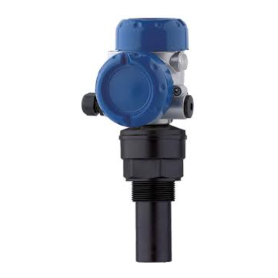
KROHNE OPTISOUND 3010 C Quick Setup Manual
Ultrasonic level transmitter four-wire 4 ... 20 ma/hart
Hide thumbs
Also See for OPTISOUND 3010 C:
- Handbook (52 pages) ,
- Quick setup manual (16 pages) ,
- Manual (16 pages)

Related Manuals for KROHNE OPTISOUND 3010 C


Summary of Contents for KROHNE OPTISOUND 3010 C
- Page 1 OPTISOUND 3010 C Quick setup guide Ultrasonic Level Transmitter Four-wire 4 … 20 mA/HART...
-
Page 2: Table Of Contents
This quick setup guide enables quick setup and commissioning of your instrument. You can find further information in the corresponding, comprehensive operating instructions as well as in the Safety Manual for instruments with SIL qualification. Operating instructions OPTISOUND 3010 C - Four-wire 4 … 20 mA/HART: Document-ID 30504 Editing status of the quick setup guide: 2019-09-25 OPTISOUND 3010 C • Four-wire 4 … 20 mA/HART... -
Page 3: For Your Safety
The safety instructions in this operating instructions manual, the na- tional installation standards as well as the valid safety regulations and accident prevention rules must be observed by the user. For safety and warranty reasons, any invasive work on the device beyond that described in the operating instructions manual may be carried out only by personnel authorised by the manufacturer. Arbi- trary conversions or modifications are explicitly forbidden. For safety reasons, only the accessory specified by the manufacturer must be used. OPTISOUND 3010 C • Four-wire 4 … 20 mA/HART... -
Page 4: Safety Label On The Instrument
A instrument according to EN 61326-1. If the instrument is used in a different environment, its electromagnetic compatibility with other devices must be ensured by suitable measures. 1.7 Fulfillment of NAMUR recommendations NAMUR is the automation technology user association in the process industry in Germany. The published NAMUR recommendations are accepted as the standard in field instrumentation. The device fulfils the requirements of the following NAMUR recom- mendations: • NE 21 – Electromagnetic compatibility of equipment • NE 43 – Signal level for fault information from measuring transduc- • NE 53 – Compatibility of field devices and display/adjustment components For further information see www.namur.de. OPTISOUND 3010 C • Four-wire 4 … 20 mA/HART... -
Page 5: Product Description
2 Product description Product description 2.1 Configuration Type label The type label contains the most important data for identification and use of the instrument: • Instrument type • Article and serial number device • Article number, documentation • Technical data: Approvals, process temperature, process fitting/ material, signal output, voltage supply, protection OPTISOUND 3010 C • Four-wire 4 … 20 mA/HART... -
Page 6: Mounting
Fig. 1: Minimum distance to the max. level Dead zone Reference plane Mounting Mount the sensor at least 200 mm (7.874 in) away from the vessel wall. > 200 mm Fig. 2: Mounting on round vessel tops Reference plane Vessel center or symmetry axis OPTISOUND 3010 C • Four-wire 4 … 20 mA/HART... -
Page 7: Connecting To Power Supply
11. Connect the lead cable for power supply in the same way accord- ing to the wiring plan, in addition connect the ground conductor to the inner ground terminal. 12. Screw the housing lid back on OPTISOUND 3010 C • Four-wire 4 … 20 mA/HART... -
Page 8: Wiring Plan, Double Chamber Housing
4 Connecting to power supply The electrical connection is finished. Wiring plan, double chamber housing Wiring plan 4...20mA L1 N 4 ... 20 mA Fig. 4: Wiring plan - double chamber housing Voltage supply Signal output OPTISOUND 3010 C • Four-wire 4 … 20 mA/HART... -
Page 9: Set Up With The Display And Adjustment Module Plicscom
The display and adjustment module is powered by the sensor, an ad- ditional connection is not necessary. Fig. 5: Insert display and adjustment module Note: If you intend to retrofit the instrument with a display and adjustment module for continuous measured value indication, a higher lid with an inspection glass is required. OPTISOUND 3010 C • Four-wire 4 … 20 mA/HART... -
Page 10: Setup Steps
Vessel form Storage tank Parameter adjustment The sensor measures the distance from the sensor to the product surface. For indication of the real level, an allocation of the measured distance to the percentage height must be carried out. The actual level is then calculated on the basis of these entered values. At the same time, the operating range of the sensor is limited from maximum range to the requested range. OPTISOUND 3010 C • Four-wire 4 … 20 mA/HART... - Page 11 3. Confirm "False signal suppression - Change now" with [OK] and select in the below menu "Create new". Enter the actual distance from the sensor to the product surface. All false signals in this area are detected by the sensor and saved after confirming with [OK]. OPTISOUND 3010 C • Four-wire 4 … 20 mA/HART...
-
Page 12: Menu Schematic
3.000 m(d) 2.000 m(d) Damping Linearisation curve Sensor-TAG Linear Sensor Display Basic adjustment ▶ Display Diagnostics Service Info Displayed value Display unit Scaling Scaled Volume 0 % = 0.0 m³ m³ 100 % = 100.0 m³ OPTISOUND 3010 C • Four-wire 4 … 20 mA/HART... - Page 13 Standard Copy sensor data? Enable? Address 0 Info Basic adjustment Display Diagnostics Service ▶ Info Instrument type Date of manufacture Last change using PC Sensor characteristics Software version Display now? Serial number 12345678 OPTISOUND 3010 C • Four-wire 4 … 20 mA/HART...
-
Page 14: Supplement
Electromechanical data Cable entry Ʋ Double chamber housing – 1 x cable gland M20 x 1.5 (cable: ø 5 … 9 mm), 1 x blind plug M20 x 1.5 – 1 x closing cap ½ NPT, 1 x blind plug ½ NPT Spring-loaded terminals for wire cross- 2.5 mm² (AWG 14) section up to Voltage supply Operating voltage Ʋ Non-Ex and Ex-d instrument 20 … 72 V DC, 20 … 253 V AC, 50/60 Hz Power consumption max. 4 VA; 2.1 W OPTISOUND 3010 C • Four-wire 4 … 20 mA/HART... - Page 15 Notes OPTISOUND 3010 C • Four-wire 4 … 20 mA/HART...
- Page 16 Products and systems for the oil and gas industry KROHNE Messtechnick GmbH & Co. KG Ludwig-Krohne-Straße 5 D-47058 Duisburg Tel.: +49 (0) 203 301 0 Tel.: +49 (0) 203 301 10389 info@krohne.de The current list of all KROHNE contacts and addresses can be found at: www.krohne.com...
Need help?
Do you have a question about the OPTISOUND 3010 C and is the answer not in the manual?
Questions and answers