
Related Manuals for Daikin FWE04FF/T


Summary of Contents for Daikin FWE04FF/T
- Page 1 Installation and operation manual Fan coil units FWE04FF/T FWE05FF/T FWE06FF/T FWE08FF/T FWE10FF/T FWE12FF/T FWE14FF/T FWE16FF/T FWE20FF/T Installation and operation manual FWE24FF/T English Fan coil units...
- Page 2 2P491002-10M...
- Page 3 4P702067-10F...
-
Page 4: Table Of Contents
▪ A subset of the latest technical data is available on the regional 12 Energy saving and optimum operation Daikin website (publicly accessible). 13 Maintenance and service ▪ The full set of the latest technical data is available on the Daikin 13.1 Maintenance safety precautions..........16 Business Portal (authentication required). -
Page 5: General
WARNING approved by Daikin unless otherwise specified. Make sure installation, servicing, maintenance and repair comply with instructions from Daikin and with applicable WARNING legislation (for example national gas regulation) and are Make sure installation, testing and applied materials executed ONLY by authorised persons. -
Page 6: For The Installer
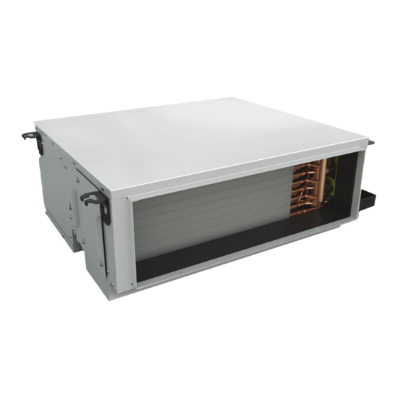
3 About the box For the installer NOTICE About the box Do NOT lift the unit by the drain pan socket (b). Keep the following in mind: ▪ At delivery, the unit MUST be checked for damage and completeness. Any damage or missing parts MUST be reported immediately to the claims agent of the carrier. -
Page 7: About The Units And Options
4 About the units and options INFORMATION About the units and options The sound pressure level is less than 70 dBA. Identification CAUTION Appliance NOT accessible to the general public. Install it in 4.1.1 Identification label: Fan coil unit a secured area, protected from easy access. This unit is suitable for installation in a commercial and Location light industrial environment. -
Page 8: Mounting The Unit
5 Unit installation Remove the cover sheet metal on the side plate of the unit. NOTICE Always use upper air purges. Mounting the unit 5.3.1 To install the suspension bolts Use the pattern to determine the suspension bolt positions (upper part of the packing). -
Page 9: To Mount The Unit
5 Unit installation 5.3.2 To mount the unit Make the required ceiling opening for installation in an applicable place. It maybe necessary to reinforce the suspended ceiling frame to keep the ceiling frame to keep the ceiling level and to prevent it from vibrating. -
Page 10: Connecting Water Piping
5 Unit installation a b c d ▪ Provide shut-off valves at the unit so that normal servicing can be accomplished without draining the system. ▪ Provide drain taps at all low points of the system to permit complete draining of the circuit during maintenance or service to the unit. -
Page 11: Drain Piping Installation
5 Unit installation a b c Drain piping installation 5.5.1 Guidelines when installing the drain piping General guidelines ▪ Pipe length. Keep drain piping as short as possible. ▪ Pipe size. Keep the pipe size equal to or greater than that of the connecting pipe (vinyl pipe of 25 ... -
Page 12: Optional Equipment Installation
5 Unit installation Plastic watering can Drain outlet (use this outlet to drain water from drain pan) Drain hose NOTICE Optional equipment installation The unit must be used with a drain hose.(Forgetting to tighten this may cause water leakages and vibrations.) 5.6.1 Preparing of optional equipment INFORMATION... -
Page 13: Connecting The Optional Equipment
6 Electrical installation 5.6.2 Connecting the optional equipment WARNING ▪ After finishing the electrical work, confirm that each Technical specifications of the valves electrical component and terminal inside the switch box is connected securely. Kvs value Max. operation Actuator power pressure PN (bar) supply ▪... -
Page 14: Connecting The Electrical Wiring
7 Commissioning 2 Pipe Frequency (Hz) Voltage (V) 220~240 Voltage tolerance (%) ±10 Wire size (cross section mm²) 0.75~1.25 Earth leakage circuit breaker Must comply with applicable legistation 6‒2 Field wiring specifications 4 Pipe Maximum operating current (A) 0.26 0.26 0.37 0.43 0,50 0.56 0.79 0.87 0.83 1.04 Maximum operating current (A) with valvesFN 0.33 0.33 0.44 0.50 0.57 0.63 0.86 0.94 0.90 1.11 Recommended overcurrent fuse (A) -
Page 15: For The User
8 User safety instructions The fuses or locally installed protection devices are There are NO loose connections or damaged electrical installed according to this document, and have NOT been components in the switch box. bypassed. There are NO damaged components or squeezed The power supply voltage matches the voltage on the pipes on the inside of the indoor and outdoor units. -
Page 16: Before Operation
10 Before operation ▪ Ventilate often. Extended use requires special attention to NOTICE ventilation. For future modifications or expansions of your system: ▪ Keep doors and windows closed. If the doors and windows remain A full overview of allowable combinations (for future open, air will flow out of your room causing a decrease in the system extensions) is available in technical engineering cooling or heating effect. -
Page 17: Precautions For Maintenance And Service
13 Maintenance and service 13.2 Precautions for maintenance and NOTICE service Do NOT use water of 50°C or higher. Possible consequence: Discoloration and deformation. NOTICE 1 Switch off the power supply. The air filter can be installed right side and left side.Remove the filter by sliding as shown below. NEVER inspect or service the unit by yourself. -
Page 18: After-Sales Service And Warranty
14 Troubleshooting 13.6 After-sales service and warranty Malfunction Measure If a safety device such as a fuse, a Turn off the main power breaker or an earth leakage breaker switch. 13.6.1 Recommended maintenance and frequently actuates or the ON/OFF inspection switch does not properly work. -
Page 19: Relocation
15 Disposal Check: If yes, Is the fan coil unit running at low Select medium speed or high speed? speed. Are the air filters dirty? Contact your installer or service company. Your fan coil unit leaks water Shut down the unit and contact your installer or service company. When your fan coil unit does not function well, you can try to solve any problem with the corrective actions in this chapter. -
Page 20: Technical Data
14, 22 Copper Technical data A subset of the latest technical data is available on the regional Daikin website (publicly accessible). The full set of the latest technical data is available on the Daikin Business Portal (authentication required). 16.1 Wiring diagram... -
Page 21: Dimensions
16 Technical data Highest speed Heating valve Cooling valve Low fan speed Medium fan speed 109 22 High fan speed Protective earth Earth Colours: OR MORE Black Blue AB AC Brown Green MODEL Orange FWE04&05&06&08& 10&12F Yellow FWE14&16&20&24F 121 Notes: : Terminal block : Field wiring. - Page 22 17 Information requirements for ecodesign Installation and operation manual FWE-F Fan coil units 3P756931-1 – 2023.11...
- Page 24 DAIKIN ISITMA VE SOĞUTMA SİSTEMLERİ SAN.TİC. A.Ş. Gülsuyu Mahallesi, Fevzi Çakmak Caddesi, Burçak Sokak, No:20, 34848 Maltepe İSTANBUL / TÜRKİYE Tel: 0216 453 27 00 Faks: 0216 671 06 00 Çağrı Merkezi: 444 999 0 Web: www.daikin.com.tr 3P756931-1 2023.11 Verantwortung für Energie und Umwelt...
Need help?
Do you have a question about the FWE04FF/T and is the answer not in the manual?
Questions and answers